- 16 -
Keyboard A500 - A500 Plus
Addressing
If installation should require two or more activation points, the keyboards installed should have different addresses, not necessarily consecutive,
and the keyboards used should be enabled based on their addresses in programming.
Example: if 3 keyboards were installed, the rst keyboard can have “address 1”, the second “address 2” and the third “address 8”.
Bear in mind that there cannot be more keypads with the same address, otherwise they will stop working and the control panel will
activate a Tamper alarm.
By simultaneously pressing keys (CLR) and (ESC), it is possible to verify the correct addressing..
In this case, the correct addresses have to be programmed in the individual keyboards in order to restore operation (see “Edit Parameters”)
If there are keyboards properly addressed, but not enabled in programming, they signal “# x not connected” on the display.
In this case, the keyboards have to be enabled when programming the central control unit in order to restore operation.
Zones / Open Collectors connected in keypad
There is the possibility to connect up to two individually programmable zone and/or open collector inputs in every keyboard (see the chapter “Types
of connection”).
A500Plus TOY Reader
A reader for managing the TOY activators is built into the A500Plus keyboard.
For operation, it sufces to program the control mode in the central control unit and acquire the TOYs to use (see the chapters “Reader on A500Plus”
and “Accesses”).
A500 Plus Audio
An audio device for executing voice communications is built into the A500Pls keyboard.
To use it, it is not necessary to connect the SPK input. All you have to do is enable the various events to communicate in the central control unit
programming (see the chapters “Keyboard” and “A500Plus Audio”)
Check that the optional DIGIVOC module is in the central control unit..
Technical Features
16-character, 2-rows display screen
Self-updating micro ash
T1 input (with 4K7 resistance and negative reference)
T2 input is not used
20 Operational keys
1= ADDR (Address): 1
2= Tamper: Enabled
3= Mode: High Speed
Edit parameters
To access the modify menu for these parameters act as follows:
a. Press the “CLR” and “ESC” buttons at the same time, the display screen will
show the programmed model, rmware version and address.
b. When pressing the “ENTER” button, the display screen will show “Enter
Unlock Code for Cong”
c. Enter code “9698”, the display screen will show” 1=ADDR, 2=TAMPER,
3=MODE”
d. Enter the number of the parameter to be congured:
1= ADDR: select the address from 1 to 16 with the “ON” and “OFF” but-
tons. Once the address is selected, press “ENTER” to conrm and return
to the menu
2= TAMPER: press “CLR” to change the parameters, press “ENTER” to
conrm and return to the menu.
3= MODE: Do not change the factory-set parameter.
e. Press “ESC” to exit from the menu
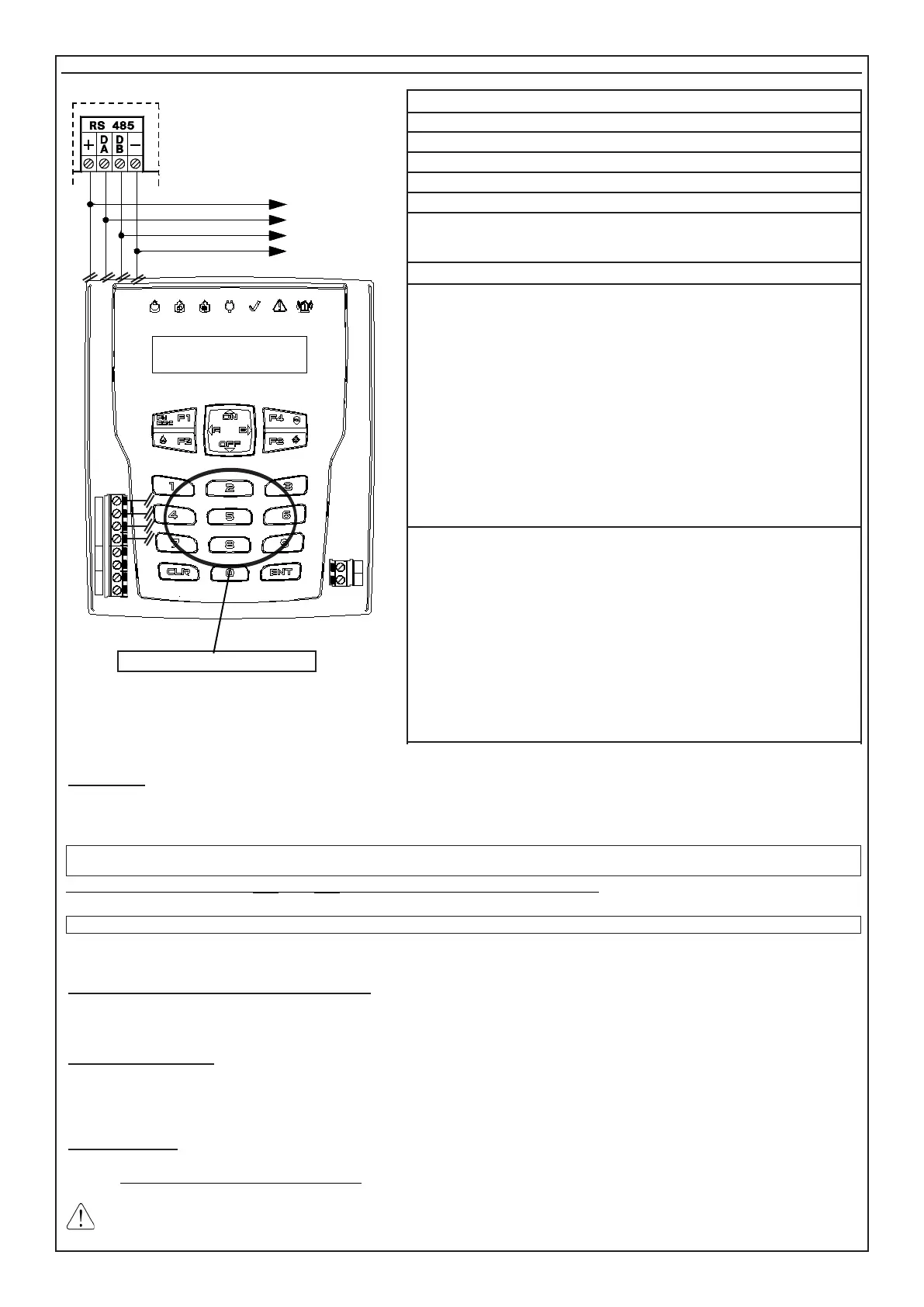
The indications in the following layout must be complied with for the connections
of the keypad, connecting the clamps of serial output RS485 of the control panel
to the corresponding keypads clamps.
• On the same serial port RS485, up to 16 keypads (mod. A500 - A500Plus)
can be connected in parallel.
• We recommend sheathed cables with four wires of 0.5 mm each.
• The total length of the connection cable can be 600 meters and must be sub-
divided for all connected electronic boards.
The signal against the opening and the tearing of the keypad from the wall is
already connected and cannot be excluded from programming; therefore, we re-
commend arranging the Tamper spring pressing on the wall correctly and carefully
closing the keypad.
Wanting to exclude button completely tamper need to change the parameter 2
in keyboard.
Se si esclude il pulsante di antimanomissione, decade l’omologazione IMQ.
DA DB
T2 T1
MIC SPK
SPEAKER
TAMPER
+
DA DB
- - -
T2 T1
TL8 L9 L10
L8 L9
TOY READER (A500Plus Only)
TOWARDS OTHER
KEYPADS