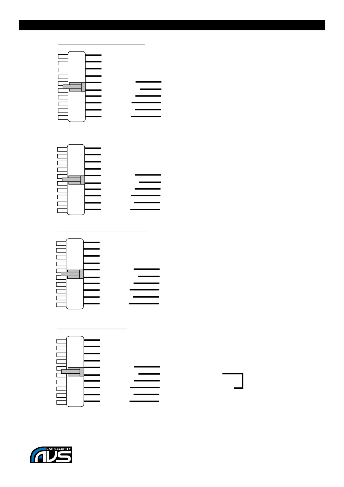
Earth
Earth
+12V (Fused 10A)
+12V (Fused 10A)
Connect to blue wire of door motor
Connect to green wire of door motor
3. Reverse Polarity CDL system:
Unlock NC
Unlock COM
Unlock NO
Lock NC
Lock COM
Lock NO
+12V (Fused 10A)
+12V (Fused 10A)
Connect to unlock wire of vehicle
Connect to lock wire of vehicle
2. Positive pulse CDL system:
Cut
Cut
Unlock NC
Unlock COM
Unlock NO
Lock NC
Lock COM
Lock NO
Earth
Earth
Connect to unlock wire of vehicle
Connect to lock wire of vehicle
1. Negative pulse CDL system:
Cut
Cut
Unlock NC
Unlock COM
Unlock NO
Lock NC
Lock COM
Lock NO
Unlock NC
Unlock COM
Unlock NO
Lock NC
Lock COM
Lock NO
Earth
+12V (Fused 10A)
Connect to Lock NC
Connect to motor end of Vacuum control wire
4. Vacuum CDL system:
Connect to switch end of Vacuum Control wire
Connect to Unlock COM
 Loading...