AXIS 210/211 Quick Installation Guide Page 3
AXIS 210/211 Network Camera
Quick Installation Guide
Package Contents
Item Notes
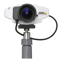
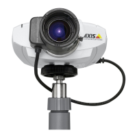
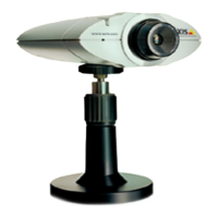
Network Camera AXIS 210 or AXIS 211.
Power adapter The adapter is country-specific. Please check that the adapter is correct for your location.
Camera stand Supplied with 3 mounting screws. The extension section is ready fitted.
Terminal block connector 4-pin. Used for connecting external devices.
CD Documentation and software.
Printed Materials • AXIS 210/211 Network Camera Quick Installation Guide
•Axis Warranty Document
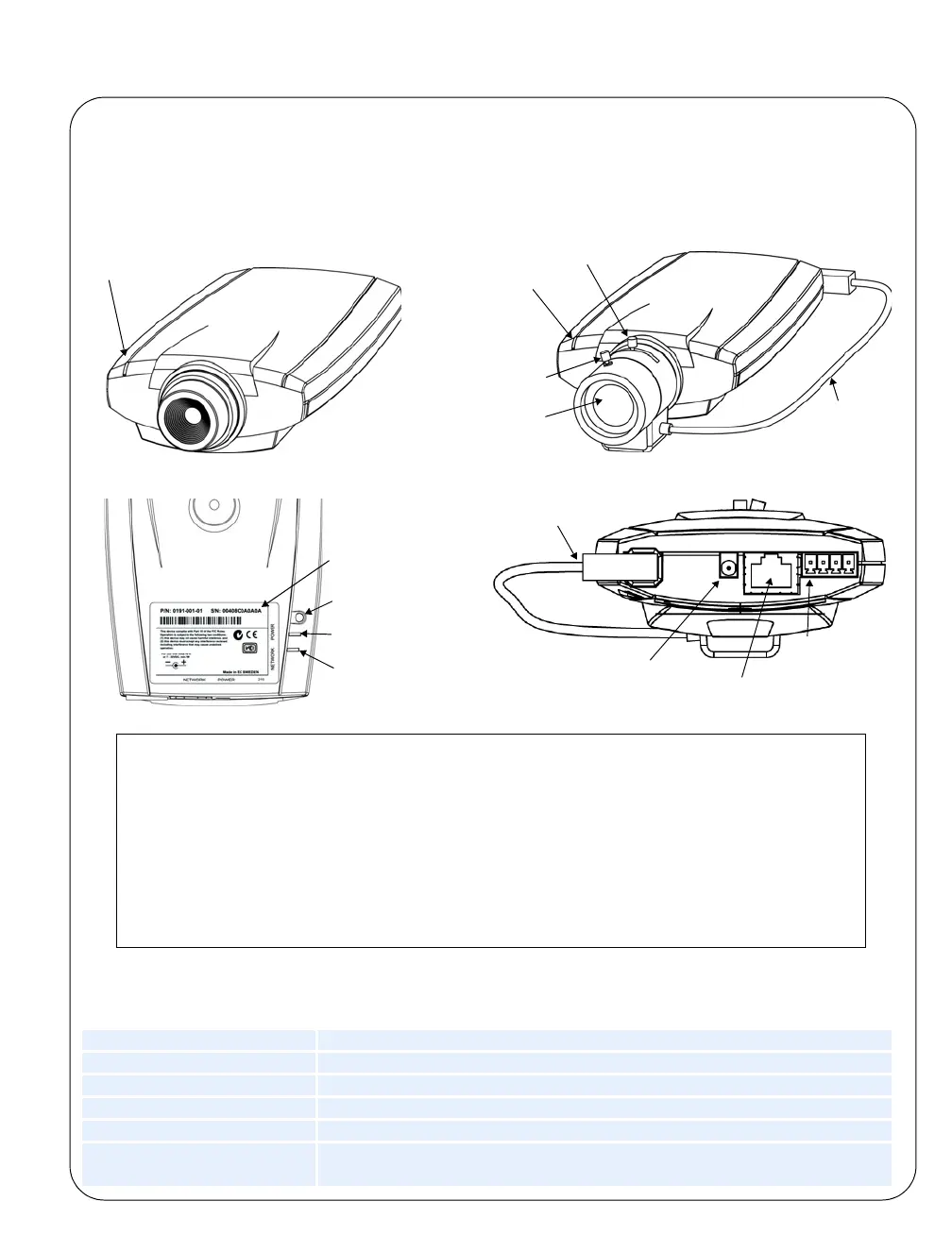
Underside
Power indicator
Network indicator
Control button
Serial number
Power connector
Network connector
DC-Iris control cable
(AXIS 211 only)
Rear panel
(and PoE for AXIS 211)
connector
I/O terminal
Status
AXIS 210
indicator
AXIS 211
DC-Iris
Focus puller
Status
indicator
Zoom puller
Control
cable
(Tele/wide)
Follow these steps to install the AXIS 210/211 on your local network (LAN):
1. Familiarize yourself with the AXIS 210/211 Network Camera (this page).
2. Connect the camera - see Cable Connections, on page 4.
3. Assign an IP address - see Installation Methods, on page 4.
For more information, please see the User’s Manual, which is available on the CD
included in this package. Updated versions can be obtained from www.axis.com