AXISA8207-VEMkIINetworkVideoDoorStation
Specifications
COM
2
Common
24VDC
3
Forpoweringauxiliaryequipment.
Note:Thispincanonlybeusedaspowerout.
Outputvoltage24VDC
Maxcurrent50mA
1
Maxcurrent350mA
2
DCground
4
0VDC
NO/NC
5
Normallyopen/normallyclosed
Forconnectingrelaydevices.
Thetworelaypinsaregalvanicallyseparatedfromthe
restofthecircuitry.
Maxcurrent1A
Maxvoltage30VDC
COM
6
Common
12VDC
7
Forpoweringauxiliaryequipment.
Note:Thispincanonlybeusedaspowerout.
Outputvoltage12VDC
Maxcurrent100mA
3
Maxcurrent700mA
4
DCground
8
0VDC
1.WhenpoweredthroughPoweroverEthernetIEEE802.3af/802.3atType1Class3.
2.WhenpoweredthroughPoweroverEthernetPlus(PoE+)IEEE802.3atType2Class4orDCpowerinput.
3.WhenpoweredthroughPoweroverEthernetIEEE802.3af/802.3atType1Class3.
4.WhenpoweredthroughPoweroverEthernetPlus(PoE+)IEEE802.3atType2Class4orDCpowerinput.
Readerconnector
4–pinterminalblockforconnectingexternalreader.
FunctionPinNotes
Specications
DCground
1
0VDC
12VDC
2
Forpoweringauxiliary
equipment.
Note:Thispincanonlybe
usedaspowerout.
Outputvoltage12VDC
D0/A+
3
Wiegand:DATA0output
RS485:A+
D1/B-
4
Wiegand:DATA1output
RS485:B-
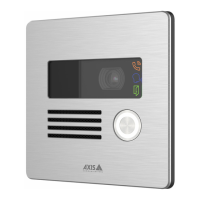
I/Oconnector
UsetheI/Oconnectorwithexternaldevicesincombinationwith,forexample,motiondetection,eventtriggering,andalarm
notications.Inadditiontothe0VDCreferencepointandpower(DCoutput),theI/Oconnectorprovidestheinterfaceto:
Digitalinput-Forconnectingdevicesthatcantogglebetweenanopenandclosedcircuit,forexamplePIRsensors,door/window
contacts,andglassbreakdetectors.
Digitaloutput-ForconnectingexternaldevicessuchasrelaysandLEDs.ConnecteddevicescanbeactivatedbytheVAPIX®
ApplicationProgrammingInterface,throughaneventorfromtheproduct’swebpage.
FunctionPinNotes
Specications
DCground
1
0VDC
24