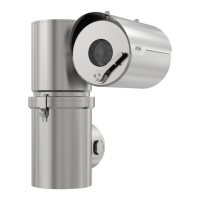
The AXIS Ex Series comprises a range of explosion-protected cameras designed for use in hazardous environments. These cameras are available in both PTZ (Pan-Tilt-Zoom) and fixed housing types, with options for visual imaging and thermal imaging. Visual cameras in the series are equipped with a wiper for maintaining clear visibility.
Housing Types and Details:
- P21 (PTZ): Features a Ø138 L210 housing and includes a wiper.
- P23 (PTZ): Features a Ø138 L210 housing and is equipped with a thermal imager.
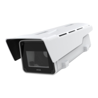
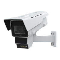
- F31xxx (Fixed): Features a Ø138 L290 housing and includes a wiper.
- F33 (Fixed): Features a Ø138 L290 housing and is equipped with a thermal imager.
The AXIS Ex Series devices are designed for safe operation in hazardous locations, but specific conditions must be adhered to:
- Flameproof Joints: Flameproof joints are not to be modified.
- Cable Temperature: Cable temperature can exceed 60 °C; suitable cables for the end application must be used.
- Cable Entries: Cable entries must utilize suitably certified cable glands, thread adaptors, or plugs that provide a minimum ingress protection rating of IP66 or IP67.
- Unused Apertures: Unused cable entry apertures must be closed with suitably certified blanking plugs.
- Protective Guard: The protective guard on thermal housings must not be removed.
- Fastener Yield Strength: The yield strength of the end cap fasteners is A4-80.
- Coal Mining Applications: For coal mining, equipment should only be installed where there is a low risk of mechanical damage from impacts that could compromise the enclosure's flameproof protection. The equipment should be placed in an area with a low risk of mechanical damage.
Installation Guidelines:
All installation and maintenance must be performed by a suitably skilled electrician in accordance with local and national standards (e.g., NFPA70, CSA C22.1, IEC/EN 60079-14, IEC/EN 60079-17).
- Technical Data: The installer must comply with the attached technical data.
- Approvals and Certifications: Ensure all items are approved and certified for environmental and installation requirements. Verify the rating label for correct ambient temperature and environmental conditions, and suitable power supply.
- Tools: Use stainless steel tools to prevent rust stains or pitting corrosion.
- Altitude: Equipment must be installed ≤2000 m above sea level.
- Modifications: Modifications or design changes are not permitted.
- Safety and Regulations: Observe all safety rules and national regulations.
- Ambient Temperature: Never install devices in areas that may exceed the ambient temperature range.
- Aggressive Substances: Aggressive substances may require extra protection.
- External Stress: If exposed to excessive external stress (vibration, heat, impact), the device must be protected by additional means.
- Manufacturer's Specifications: The device's protection may be impaired if not utilized as specified by the manufacturer.
- Cables and Glands: Incoming cables must comply with national standards. Suitably certified cable glands and blanking plugs must be used. Thread form must be M25x1.5 or M20x1.5 (tolerance 6g/6H according to ISO 965). The cable gland must not invalidate the enclosure's IP rating and must be rated for the installation.
- P21 Cable Glands: Devices of type P21 must use CMP type PXSS2K cable glands. Recommended cable glands include Ex d Cable Gland M20 armored cable and Ex d Cable Gland M20 non-armored cable.
- Plugs: All entries must be plugged with suitable certified equipment.
- Fixing Brackets: Tighten fixing brackets upon installation using suitable screws, considering the product's weight (refer to datasheet).
- Replacement Parts: Only component parts specified by Axis Ex AB may be used for replacement.
- Clearance: Distances between flamepaths and sunshield, and between flamepaths and any other obstruction (e.g., wall or ceiling), have been considered in ATEX/IECEx and North American certifications, requiring no minimum clearance for hazardous environment installation.
Wiring:
Electrical installation and servicing must be performed by skilled persons.
- AC Mains Supply: Should include a circuit breaker rated maximum 20 A.
- Surge Protector: A surge protector device is required as part of the installation to prevent transient overvoltage exceeding 2500 Vpk.
- Mains Disconnect: AC mains electrical supply must have a readily accessible all-pole mains disconnect device provided as part of the building installation.
- Protective Earth: The device must be connected to protective earth through the internal earth terminal connection.
- External Earthing Points: For supplemental bonding only where local authorities permit or require such a connection.
- Earth Connection Ferrule: Must be of a suitable material to avoid corrosion.
- Power Disconnect: Disconnect the device from the power source before any operations.
- Voltage Verification: Ensure correct voltage before maintenance or connections.
- Conductor Identification: Use suitably color-coded conductors or other identification means.
- Earthing Conductors: Should be green and yellow.
- Thread Form: Take extra care not to damage the thread form.
Wiring of P21 and P23:
Connect the PTZ camera wiring to the connection chamber at the base of the device.
- Remove the two locking grub screws using the included stainless steel bits.
- Remove the threaded chamber cover using the included removal tool to avoid thread damage.
- Route cables through threaded entry points and suitably certified glands.
- Earthing Connection: Minimum 14 AWG (2 mm²) conductor with green and yellow insulation. Connect through the M4 earth stud using the supplied crimp ring terminal. Tighten with a 7 mm ring spanner or socket.
- Terminal Plugs: Can be disconnected for easy termination outside the enclosure. For TB1 and TB2, use wire between 18-12 AWG (0.8-3.0 mm²).
- Clamping Points: Only one wire should be connected to each clamping point.
- External Earth Connection: Available for up to 11 AWG (4 mm²) connection. When used, it should be with a crimp ring terminal.
- Network Connection: Use an RJ45 connector (CAT5 or higher). An SFP slot is optionally available for an additional network connection, utilizing various SFP modules including fiber optic.
- Fiber Optic Cable: Use of fiber optic cable and internal connections must comply with UL/IEC/EN 60079-14 requirements.
- Cover Fastening: After wiring, fasten the threaded chamber cover and tighten until the joint is closed. Tighten the two locking grub screws using the included stainless steel bits.
Wiring of F31 and F33:
Connect the fixed camera wiring to the connection terminal at the back of the device.
- Remove the 6 M5x12 A4 socket head screws using the included stainless steel bits.
- Remove the back cover, carefully pulling it off.
- Route the cables through threaded entry points and suitably certified glands.
- Joint Surface: Take extra care not to damage the joint surface.
- Earthing Connection: Minimum 14 AWG (2 mm²) conductor with green and yellow insulation. Connect through the M4 earth stud using the supplied crimp ring terminal. Tighten with a 7 mm ring spanner or socket.
- Terminal Plugs: Can be disconnected for easy termination outside the enclosure. For TB1 and TB2, use wire between 18-12 AWG (0.8-3.0 mm²).
- Clamping Points: Only one wire should be connected to each clamping point.
- External Earth Connection: Available for up to 11 AWG (4 mm²) connection. When used, it should be with a crimp ring terminal.
- Network Connection: Use an RJ45 connector (CAT5 or higher). An SFP slot is optionally available for an alternative network connection, utilizing various SFP modules including fiber optic.
- Power over Ethernet (PoE): The RJ45 network connection can supply power. When using PoE, the Power Sourcing Equipment (PSE) must comply with IEEE 802.3bt type 3 Class 6 PoE.
- Fiber Optic Cable: Use of fiber optic cable and internal connections must comply with UL/IEC/EN 60079-14 requirements.
- Cover Fastening: After wiring, fit the back cover. Tighten the 6 M5x12 A4 socket head screws to 6 Nm ±0.5 torque using the included stainless steel bits.
Maintenance:
The device contains no serviceable parts. Covers or seals should not be removed.
- Repairs: It is strictly prohibited to attempt repairs unless performed by approved and trained personnel.
- Fasteners: Check all mounting fasteners for tightness at regular intervals.
- Cleaning: To maintain smooth operation, clean the device regularly with water, mild detergent, and a soft cloth.
Battery (for F31111 devices):
Devices of type F31111 use a 3.0 V BR2330A lithium battery to power the internal real-time clock (RTC). This battery typically lasts a minimum of five years. Low battery power affects RTC operation, causing it to reset at every power-up. A log message will appear in the product's server report when battery voltage is low.
- Battery Replacement: Do not replace the battery yourself. Contact Axis support if a battery change is requested by a log message.
- Battery Composition: Lithium coin cell 3.0 V batteries contain 1,2-dimethoxyethane; ethylene glycol dimethyl ether (EGDME), CAS no. 110-71-4.
Important Technical Specifications (Example for P21):
- Ingress Protection: IP66/IP67/68, Type 4X
- Voltage:
- PTZ: 100 - 240 V AC ±10%
- Fixed: 100 - 240 V AC ±10%, PoE 802.3bt Type 3
- Power:
- Frequency: 50 - 60 Hz
- Entry Thread Size:
- PTZ: M25
- Fixed: M25 and M20
- Ambient Temperature: -60 °C to +60 °C (F31111: -40 °C to +60 °C)
- Hazardous Area Ratings (Example):
- I M2 Ex db I Mb
- II 2 G Ex db IIC T6-T4 Gb
- II 2 D Ex tb IIIC T85°C - T135°C Db
- Class I Div 1 Groups B, C, D T6-T4
- Class II Div 1 Groups E, F, G T6-T4
- Class I Zone 1 AEx db IIC T6-T4 Gb
- Zone 21 AEx tb IIIC T85°C – T135°C Db
- Class III Div 1
- Certificate Numbers (Example):
- ATEX: ExVeritas 20 ATEX 0651X
- IECEx: EXV 20.0017X
- MET: E115198
Dimensions:
- P21 and P23 (PTZ):
- Overall height: 380mm [14.97"]
- Width (housing): Ø153mm [Ø6.02"]
- Depth (housing): 243mm [9.57"]
- Total depth (including bracket): 302mm [11.90"]
- Mounting holes: 72mm [2.83"] apart, M10
- Cable entries: M25x1.5 (2x)
- F31 and F33 (Fixed):
- Overall length: 342mm [13.48"]
- Width (housing): Ø160mm [Ø6.30"]
- Height (housing): 168mm [6.62"]
- Mounting holes: 76mm [2.99"] and 126mm [4.94"] apart, M6
- Cable entries: M25x1.5 (2x), M20x1.5 (2x)
- The user manual is available at axis.com.
- Firmware updates can be checked at axis.com/support.
- Online trainings and webinars are available at axis.com/academy.
Axis Ex AB
Gränden 1
223 69 Lund
Sweden
Tel: +46 46 272 18 00
Fax: +46 46 13 61 30
axis.com