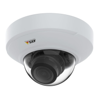
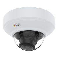
AXISM43SeriesPanoramicCamera
Specifications
Buttons
Controlbutton
Thecontrolbuttonisusedfor:
•Resettingtheproducttofactorydefaultsettings.SeeResettofactorydefaultsettingsonpage60.
Intrusionalarmswitch
Usetheintrusionalarmswitchtogetanoticationwhensomeoneopensthedevice’shousing.Createaruletomakethedevice
performanactionwhentheswitchisactivated.SeeTriggeranalarmifsomeoneopensthehousingonpage16.
Connectors
Networkconnector
RJ45EthernetconnectorwithPoweroverEthernet(PoE).
I/Oconnector
UsetheI/Oconnectorwithexternaldevicesincombinationwith,forexample,motiondetection,eventtriggering,andalarm
notications.Inadditiontothe0VDCreferencepointandpower(12VDCoutput),theI/Oconnectorprovidestheinterfaceto:
Digitalinput-Forconnectingdevicesthatcantogglebetweenanopenandclosedcircuit,forexamplePIRsensors,door/window
contacts,andglassbreakdetectors.
Supervisedinput-Enablespossibilitytodetecttamperingonadigitalinput.
Digitaloutput-ForconnectingexternaldevicessuchasrelaysandLEDs.ConnecteddevicescanbeactivatedbytheVAPIX®
ApplicationProgrammingInterface,throughaneventorfromthedevice’swebinterface.
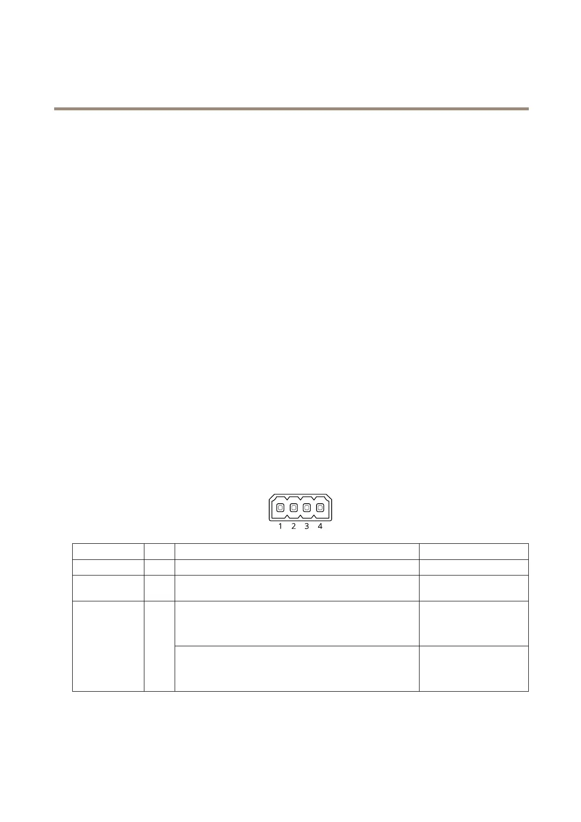
4-pinterminalblock
FunctionPinNotes
Specications
DCground
1
0VDC
DCoutput
2
Canbeusedtopowerauxiliaryequipment.
Note:Thispincanonlybeusedaspowerout.
12VDC
Maxload=50mA
DigitalinputorSupervisedinput–Connecttopin1toactivate,or
leaveoating(unconnected)todeactivate.Tousesupervisedinput,
installend-of-lineresistors.Seeconnectiondiagramforinformation
abouthowtoconnecttheresistors.
0tomax30VDC
Congurable
(InputorOutput)
3–4
Digitaloutput–Internallyconnectedtopin1(DCground)when
active,andoating(unconnected)wheninactive.Ifusedwithan
inductiveload,e.g.,arelay,connectadiodeinparallelwiththeload,
toprotectagainstvoltagetransients.
0tomax30VDC,opendrain,
100mA
Example
57