AXISP1365NetworkCamera
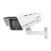
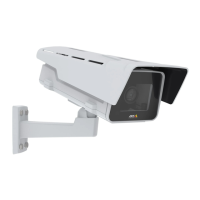
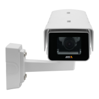
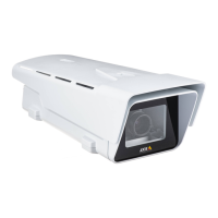
HardwareOverview
HardwareOverview
4 52 3
1
6
14
15
16
10
11
12
13
7 8 9
1
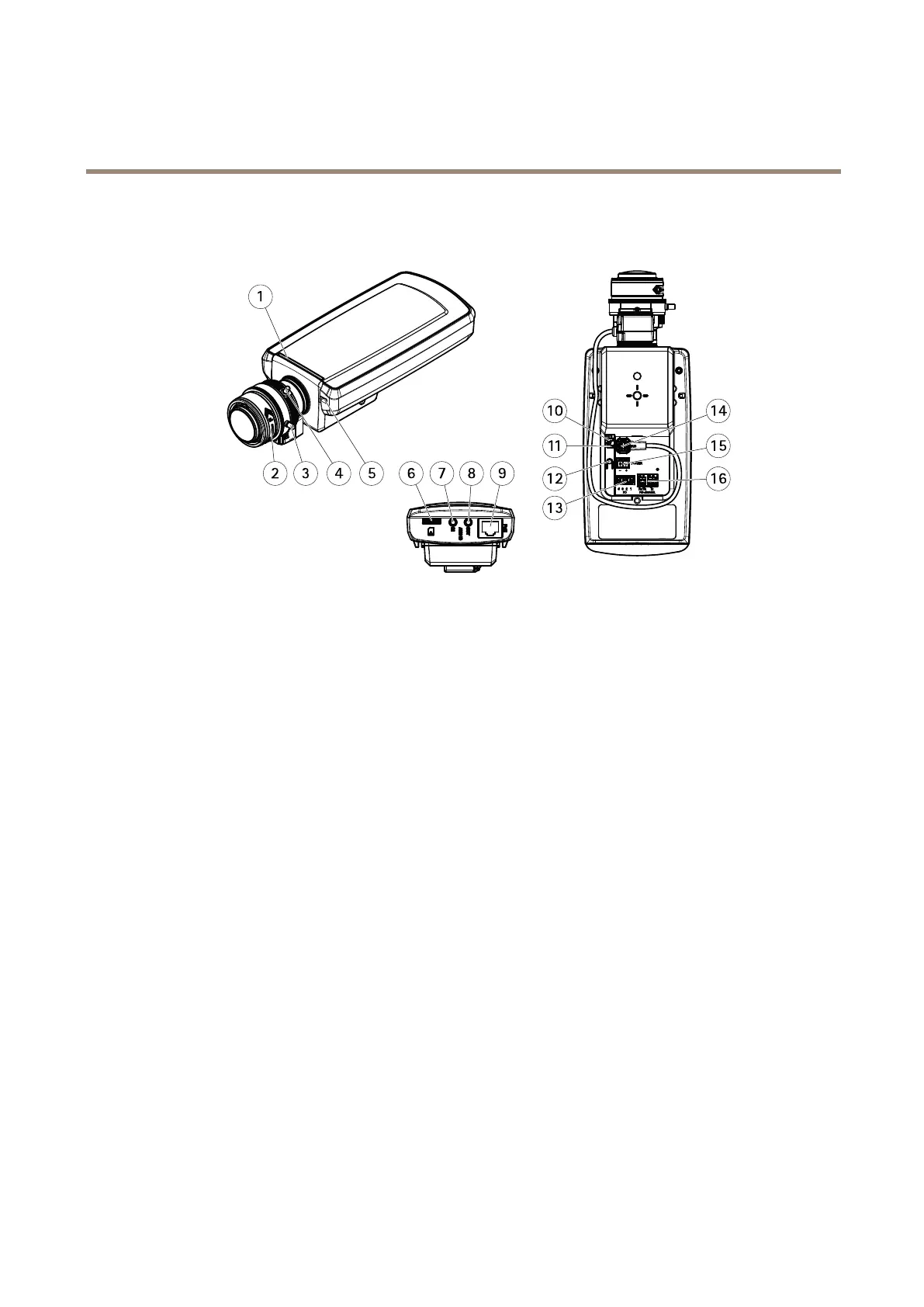
StatusLED
2
Focusring
3
Lockscrewforfocusring
4
Zoompuller
5
Built-inmicrophone
6
microSDcardslot
7
Audioin
8
Audioout
9
Networkconnector(PoE)
10
PowerLED
11
NetworkLED
12
Controlbutton
13
I/Oconnector
14
Irisconnector
15
Powerconnector
16
RS485/422connector
ConnectorsandButtons
Fortechnicalspecications,seepage67.
NetworkConnector
RJ45EthernetconnectorwithPoweroverEthernet(PoE).
I/OConnector
Usewithexternaldevicesincombinationwith,forexample,tamperingalarms,motiondetection,eventtriggering,timelapserecording
andalarmnotications.Inadditiontothe0VDCreferencepointandpower(DCoutput),theI/Oconnectorprovidestheinterfaceto:
•Digitaloutput–ForconnectingexternaldevicessuchasrelaysandLEDs.Connecteddevicescanbeactivatedbythe
VAPIX®ApplicationProgrammingInterface,outputbuttonsontheLiveViewpageorbyanActionRule.Theoutputwill
showasactive(shownunderSystemOptions>Ports&Devices)ifthealarmdeviceisactivated.
7