AXISP1427–LENetworkCamera
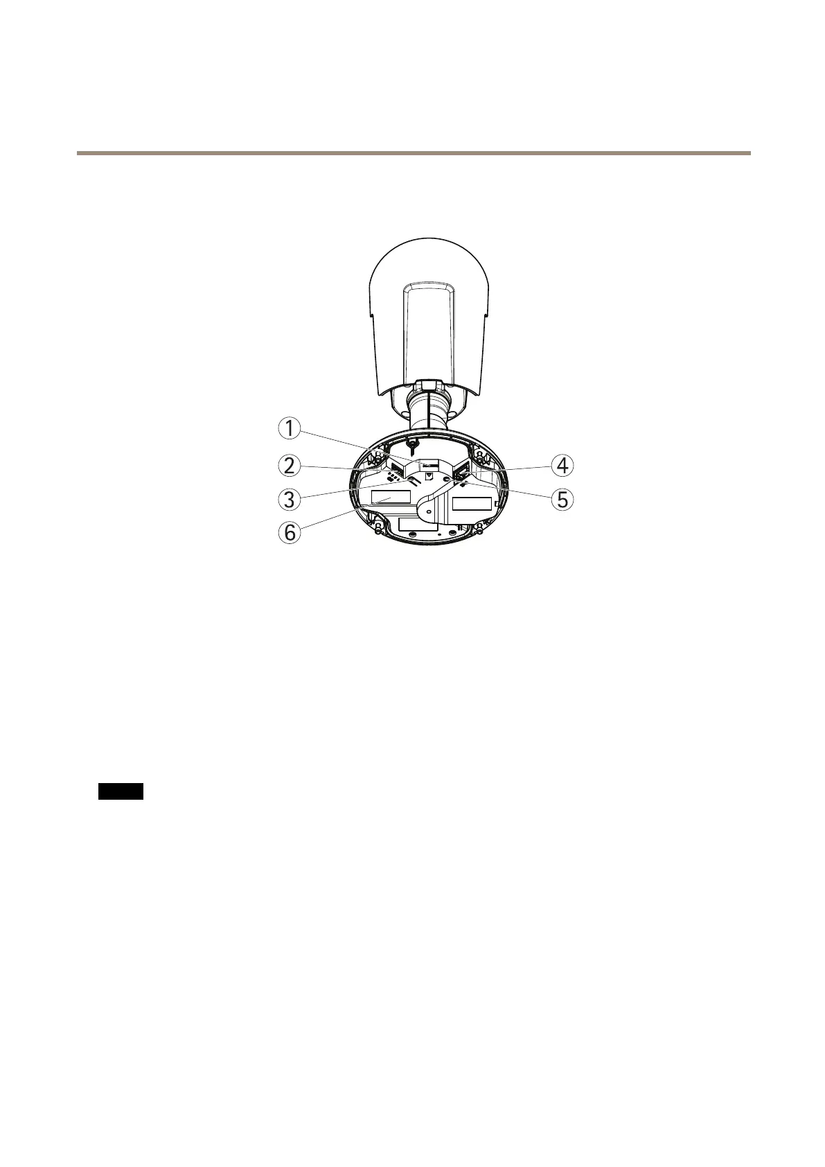
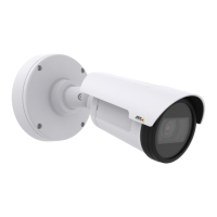
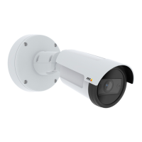
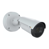
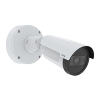
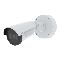
HardwareOverview
HardwareOverview
1
microSDcardslot
2
I/Oconnector
3
Controlbutton
4
Networkconnector
5
StatusLEDindicator
6
Partnumber(P/N)&Serialnumber(S/N)
ConnectorsandButtons
Fortechnicalspecications,seepage62.
NetworkConnector
RJ45EthernetconnectorwithPoweroverEthernet(PoE).
NO NO
NO
TICE TICE
TICE
Duetolocalregulationsortheenvironmentalandelectricalconditionsinwhichtheproductistobeused,ashieldednetwork
cable(STP)maybeappropriateorrequired.Allcablesconnectingtheproducttothenetworkandthatareroutedoutdoors
orindemandingelectricalenvironmentsshallbeintendedfortheirspecicuse.Makesurethatthenetworkdevices
areinstalledinaccordancewiththemanufacturer’sinstructions.Forinformationaboutregulatoryrequirements,see
ElectromagneticCompatibility(EMC)onpage2.
I/OConnector
Usewithexternaldevicesincombinationwith,forexample,tamperingalarms,motiondetection,eventtriggering,timelapserecording
andalarmnotications.Inadditiontothe0VDCreferencepointandpower(DCoutput),theI/Oconnectorprovidestheinterfaceto:
•Digitaloutput–ForconnectingexternaldevicessuchasrelaysandLEDs.Connecteddevicescanbeactivatedbythe
VAPIX®ApplicationProgrammingInterface,outputbuttonsontheLiveViewpageorbyanActionRule.Theoutputwill
showasactive(shownunderSystemOptions>Ports&Devices)ifthealarmdeviceisactivated.
7