AXIS P5532/P5534 Installation Guide Page 21
ENGLISH
• Digital input - An alarm input for connecting devices that can toggle between an open and
closed circuit, for example: PIRs, door/window contacts, glass break detectors, etc. When a
signal is received the state changes and the input becomes active (shown under
Events > Port Status).
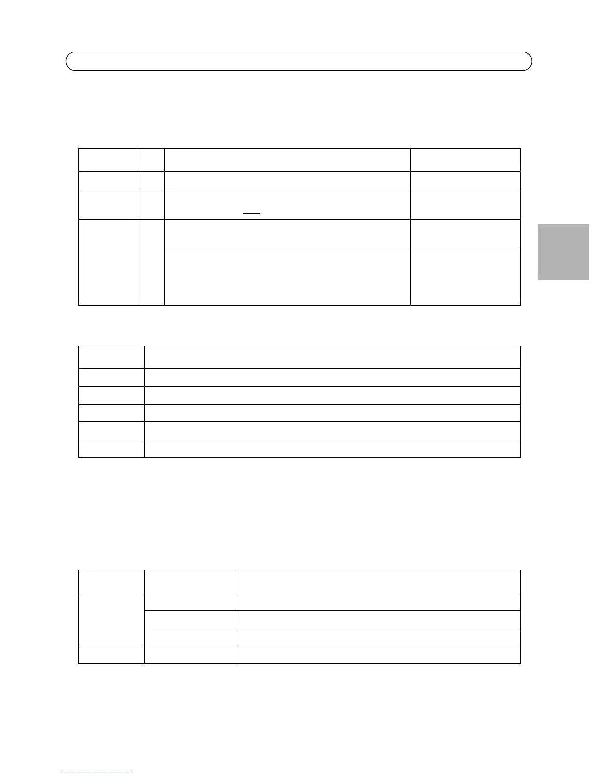
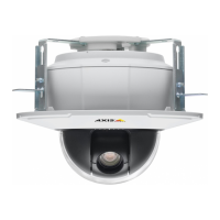
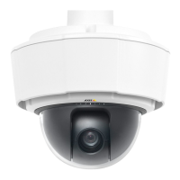
AXIS P5532/P5534 Status indicators
Note:
For more information on the AXIS P5532/P5534 status indicators, please see the User’s
Manual available from the AXIS Network Video Product CD supplied with this product or
from the website at www.axis.com
AXIS T8123 Status indicators
Function Pin Notes Specifications
GND 1 Ground
3.3 V DC
Power
2 Can be used to power auxiliary equipment.
Note: This pin can only
be used as power out.
Max. load = 250 mA
Configurable
(input or
Output)
3-6 Digital input – Connect to GND to activate, or leave floating
(unconnected) to deactivate.
Min. input = -40 V DC
Max. input = +40 V DC
Digital output – Uses an open-drain NFET transistor with the
source connected to GND. If used with an external relay, a
diode must be connected in parallel with the load, for pro-
tection against voltage transients.
Max. load = 100 mA
Max. voltage = +40 V DC
Color Indication
Unlit Steady connection/normal operation
Amber Steady during system initiating and reset to factory default. Flashes during firmware upgrade.
Amber/red No network connection
Red Firmware upgrade failure
Green Steady for 10 sec. after successful restart
LED Color Indication
Port Unlit No camera connected
Flashing Power overload or other input voltage error
Green Camera connected, normal behavior
AC input Steady green AC power connected