41
AXIS P5532/AXIS P5534 - Multi-Connector Cable (not included)
Multi-Connector Cable (not included)
When connecting external equipment to AXIS P5532/AXIS P5534, a multi-connector cable (available from Axis) is required in
order to maintain the camera’s IP51 rating. The multi-connector cable can be purchased from your Axis reseller.
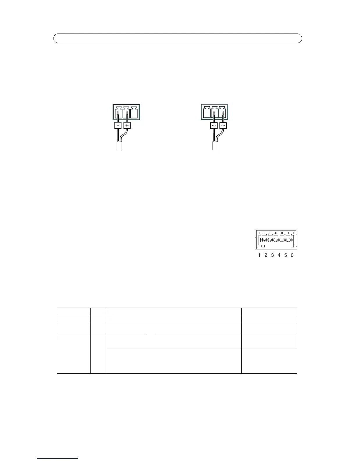
Connect the multi-connector cable to the camera’s multi-connector (see page 5). The cable provides the following connectors:
Power connector - 3-pin terminal block used for power input.
Audio in (pink) – 3.5 mm input for a mono microphone, or a line-in mono signal (left channel is used from a stereo signal).
Audio out (green) – 3.5 mm output for audio (line level) that can be connected to a public address (PA) system or an active
speaker with a built-in amplifier. A pair of headphones can also be attached. A stereo connector must be used for the audio
out.
I/O terminal connector - Used in applications for e.g. motion detection, event triggering, time
lapse recording and alarm notifications. In addition to an auxiliary power and a GND pin, the I/O
terminal connector has 4 pins that can be configured as either input or output. These pins provide
the interface to:
• Digital output - For connecting external devices such as relays and LEDs. Connected
devices can be activated by the VAPIX® Application Programming Interface, output buttons on the Live View page or
by an Event Type. The output will show as active (shown under Events > Port Status) if the alarm device is activated.
• Digital input - An alarm input for connecting devices that can toggle between an open and closed circuit, for exam-
ple: PIRs, door/window contacts, glass break detectors, etc. When a signal is received the state changes and the input
becomes active (shown under Events > Port Status).
Note:
Pin 3 is I/O Port 1, pin 4 is I/O Port 2, pin 5 is I/O Port 3 and pin 6 is I/O Port 4.
Function Pin Notes Specifications
GND 1 Ground
3.3 V DC
Power
2 Can be used to power auxiliary equipment.
Note: This pin can only
be used as power out.
Max load = 250 mA
Configurable
(Input or
Output)
3-6 Digital input – Connect to GND to activate, or leave floating
(unconnected) to deactivate.
Min input = -40 V DC
Max input= +40 V DC
Digital output – Uses an open-drain NFET transistor with the
source connected to GND. If used with an external relay, a diode
must be connected in parallel with the load, for protection against
voltage transients.
Max load =100 mA
Max voltage = +40 V DC