17
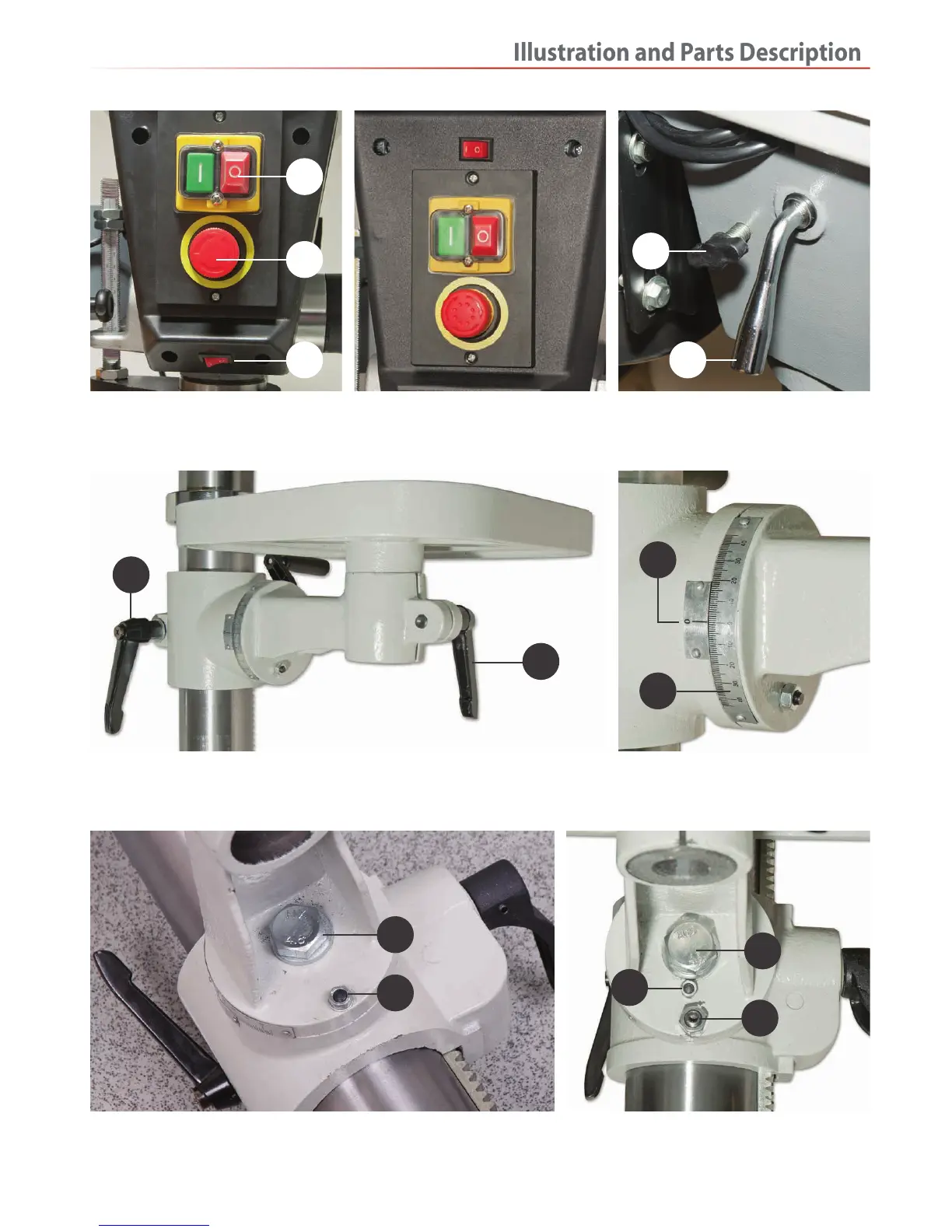
On/Off switch (A)
Emergency stop button (B)
LED light switch (C)
ATDP20F pillar drill control panel
NOTE: The LED light switch is above
the On/Off switch assembly
Motor yoke butterfly lock (A)
Drive belt tensioning lever lock (B)
Lift and shift handle (A) for securing the table mounting arm
Clamping handle (B) for securing the table
Table tilt clamping bolt (A), 90˚ degrees locking pin (B) ATDP20F Pillar drill table tilt assembly
Table tilt clamping bolt (A)
90˚ degree locking pin (B)
Table levelling adjusting nut (C)
Table tilt pointer (A)
Table tilt scale (B)
A
B
C B
A
A
B
B
A
A
A
C
B
B
 Loading...