WHITE
AXMINSTER
W
21
Setting Up the Saw...
FREEPHONE 0800 371822
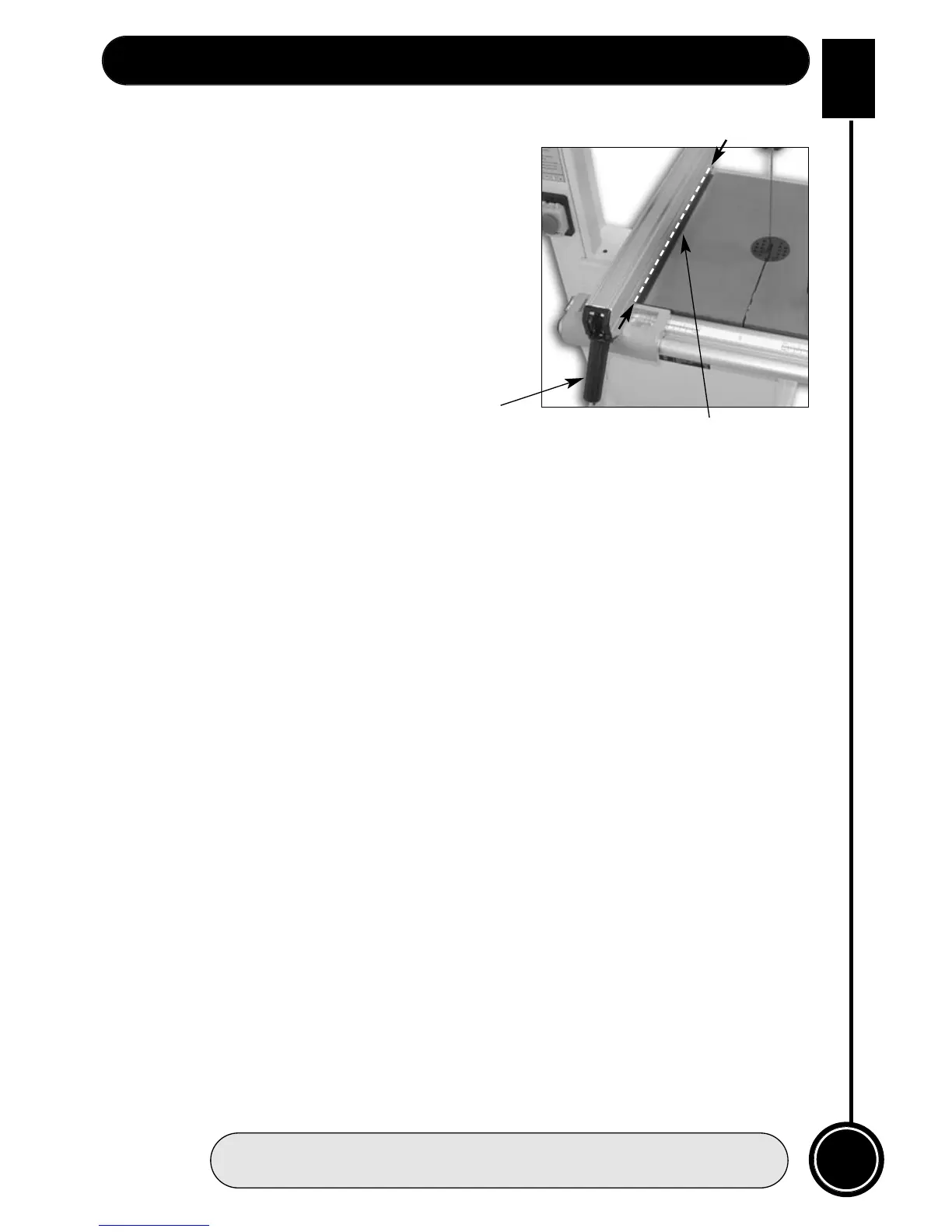
Setting the fence
1. Clamp down the fence by pushing the locking
lever down.
2. Loosen the fence rail by undoing
the four hex bolts. (See fig 1a)
3. Adjust the fence rail until the guide fence rail is
in line with the table slot. (See fig 14) Re-tighten
the hex bolts. (Do Not overtighten) then unlock
the fence by lifting the locking lever up.
Setting the blade guides
Lower the upper blade guide to approximately 1
1
/2
”(38mm) above the table. Clamp in place.
Loosen the two bolts marked ‘A’ (see fig 10) holding the guide assembly in place and adjust
the back to front position so that the leading edges of the side guide bearings are
approximately 1.5 mm behind the gullets of the saw blade. Re-tighten the bolts. Loosen the
cross point screw (see fig 9) in the rear bearing clamp and adjust the thrust bearing to
approximately 1mm behind the blade, tighten the screw.
(Note that the rear thrust bearing is mounted on a ‘cranked’ arm which can pivot; ensure
that when you clamp the arm in position, the blade is running approximately midway
between the centre and the outside edge of the bearing). (Check the symmetry with the
bottom thrust bearing).? Loosen the two bolts (marked ‘B’ fig 10) holding the guide
bearings (10mm spanner) and move to approximately 0.5 mm from each side of the blade.
Tighten the bolts. Gently push the blade back against the thrust bearing (use a scrap of
wood, et al,) and check that the side bearings are still behind the teeth of the blade. Loosen
the bolt (bolt ‘C’ fig 12) holding the lower blade guide assembly in place and position
similarly to the upper guide assembly. Tighten the bolt. Loosen the clamping screw (screw
‘D’ see fig12) of the rear thrust bearing (cross point screwdriver). Move it forward until it
touches the back of the blade; gently push the blade back against the upper thrust bearing,
this should move the lower thrust bearing back in line with upper bearing; tighten the
clamping screw. Adjust the lower side blade guides, and set them similarly to the upper
guides, using a cross point screwdriver to release and tighten the clamping screws
(marked ‘E’ fig 12). (You may find it easier to adjust the lower guide assembly if you remove
the plastic safety box that is screwed to the lower guide mounting. Remove by unfastening
the screw shown in (fig.11). Replace after all adjustments have been made. When all
adjustments have been made, recheck that when the blade is pressed back against the
thrust bearings, both the upper and lower side guides are still behind the teeth of the saw.
(This is imperative in the case of the lower guides as these are steel rods, and if they
impact with the saw teeth…………. I leave it to your imagination.).
When all adjustments are complete replace the table insert. Re-connect the power, switch
the saw on, allow to run for several minutes, check that the blade is still tracking correctly,
there is no excessive vibration, etc., etc. Switch off. The saw is ready to be used. Now
please read the Instruction Manual.
Fig 14
Table ‘T’ slot
Locking lever