Axon Fleet 2 Installation Manual
Axon Enterprise, Inc. Page 27 of 39
4. On the Axon Fleet power unit end, remove the male end of the connector.
5. Unscrew the small set screws.
6. Strip no more than 0.25″ (6.35 mm) of insulation from each of the wires.
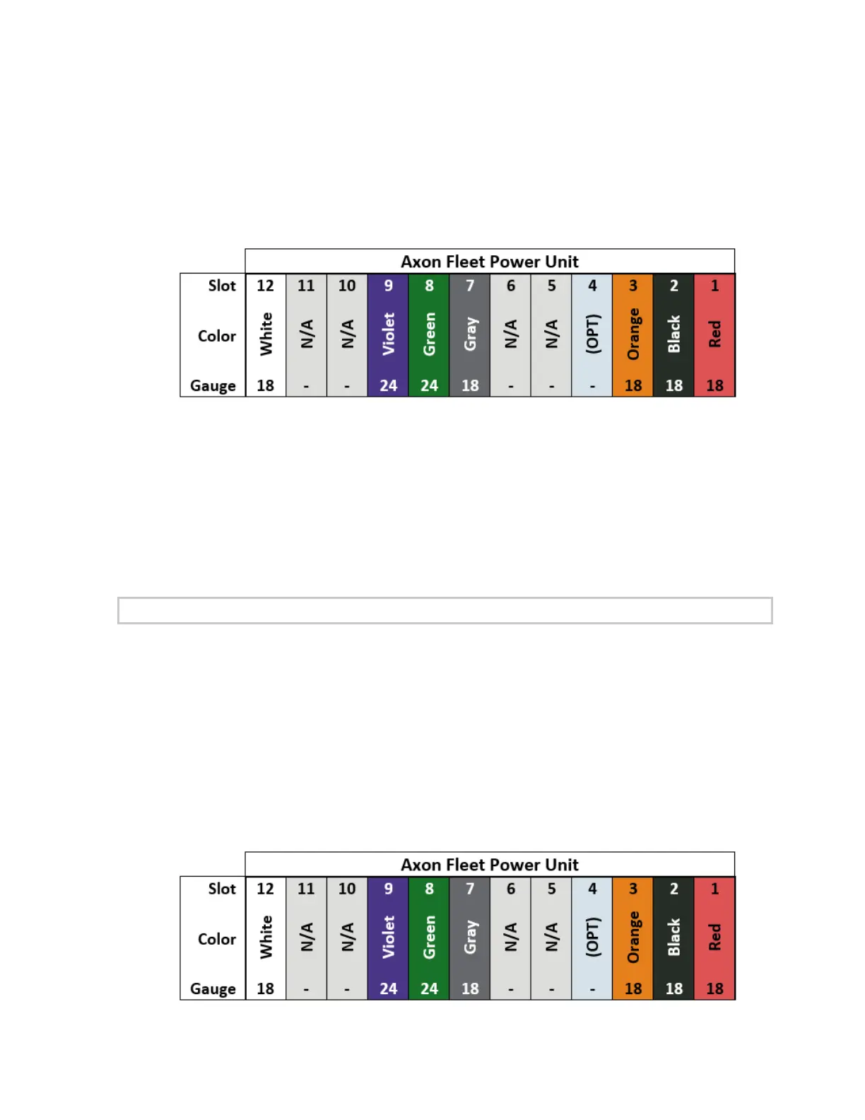
7. Insert the stripped wires into the appropriate slot on the power unit.
• Orange – 3 (Ignition – Motor On)
• Black – 2 (Ground)
• Red – 1 (12 VDC Power)
• OPT – 4 (optional Ignition – Accessory connection)
8. Tighten down the set screws.
Axon Fleet Power Unit to Camera/Controller Mount
Note: If the installation does not require the full length of the power unit to
camera/controller mount wiring harnesses, then cut the harnesses as needed to fit the
installation.
1. Once the Wiring harness has been run to the desired location of the power unit, strip no
more than 0.25″ (6.35 mm) of insulation from each of the wires.
2. Unscrew the small set screws.
3. Insert the stripped wires into the appropriate slot on the power unit.
 Loading...
