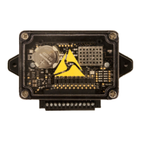
Wiring instructions
System power (positions 1–2)
Axon recommends using a red wire for the power connection and a black wire for ground
connection.
1. Connect J2-1 to a Positive (+) 12 VDC source from the vehicle battery using an 18 AWG
red wire. Axon recommends installing a 1A fuse, either inline or on a fuse block, for this
position.
2. Connect J2-2 to the vehicle’s chassis ground using an 18 AWG black wire. This is
typically adjacent to the battery.
Ignition enable (position 3)
Connect J2-3 terminal to the vehicle’s ignition voltage. This will allow Axon Signal Vehicle to
be turned on with the ignition switch.
Optional auxiliary enable (position 4)
The J2-4 input provides an alternate signal to Axon Signal Vehicle for enabling the system.
Either the
Ignition enable
or
Optional auxiliary enable
input is required for the device to turn
on. Both inputs may be used simultaneously to allow for greater flexibility in enabling
options. Axon Signal Vehicle must be wired in a manner such that voltage for either
enable
position is removed prior to removal of system power. Consequently,
system power
and
enable
nodes must not be wired from the same source.
Trigger input (positions 5–12)
1. Turn on the trigger source, such as light bar control signal.
2. Using a voltmeter, ensure the wire connected to the trigger source has 3.6–14.4 VDC
present while the trigger is enabled.
3. Turn the trigger off and verify that the voltage drops to zero. For Axon Signal Vehicle to
work optimally, the trigger should provide a constant voltage to the device when it is
activated.
4. Connect the trigger source to one of the input terminals on the Axon Signal Vehicle J2
connector.
5. Up to eight independent trigger sources can be wired directly to Axon Signal Vehicle.
Wire inputs that originate from progressive slide switches to inputs J2-11 or J2-12.
Signal Vehicle User and Installation Guide
Axon Enterprise, Inc. 5

 Loading...