Solenoid valve controller
Function
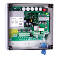
Jumper XS1 Terminal* Note
Cleaning mode
∆p-Threshold control Schw.
Pause time control Reg.
External-∆p-signal Reg. 17,18 external signal only pause time control
Timer mode Schw. 16, 17 connected Pulse- and pause poti
* Terminals 18, 19 connected = release
•
Push-button S1: Starts cleaning with the next valve, terminates the pause of the
(‘Test’) current valve. If 'total cycle' is selected, cleaning is carried out up
to the last valve.
•
LED-indicators: Operation (green) or malfunction (red)
Cleaning (yellow)
Pulse indication for each valve (red)
•
Valve error The valve LED flashes.
indication: Cause: short-circuit, breakage or error at mechanically
valve function monitoring with pressure switch
4.2 Inputs
Analog: Start or ∆p-Input 0(4)…20 mA
The analogue signal is measured between terminal 17 + and terminal
18 - (GND). Terminal 16 can be used as an auxiliary current source
(25 mA)
Timer mode: Term. 16 and 17 connected
Digital: Release (contact closed) / Stop (contact open)
Post-cleaning (signal from push-button)
Malfunction acknowledgement (signal from push-button)
Pressure switch for mechanical checking of the valve function.
The inputs are active if they are switched to ground (terminal 18 GND).
4.3 Outputs
Valves: 1...12 with 24 VDC / 1A (extensible to 1...24 valves)
+ Outputs have common potential
- outputs are switched
Relays: Contact rating 250 VAC / 5 A
1 change over contact for operating/malfunction message
(fail-safe-circuit)
1 normally open contact for cleaning message
The inputs and the analogue output are not galvanically separated!
Provide an external potential separation, if required!
 Loading...