∆p-Extension (Option)
5 ∆p-Extension (Option)
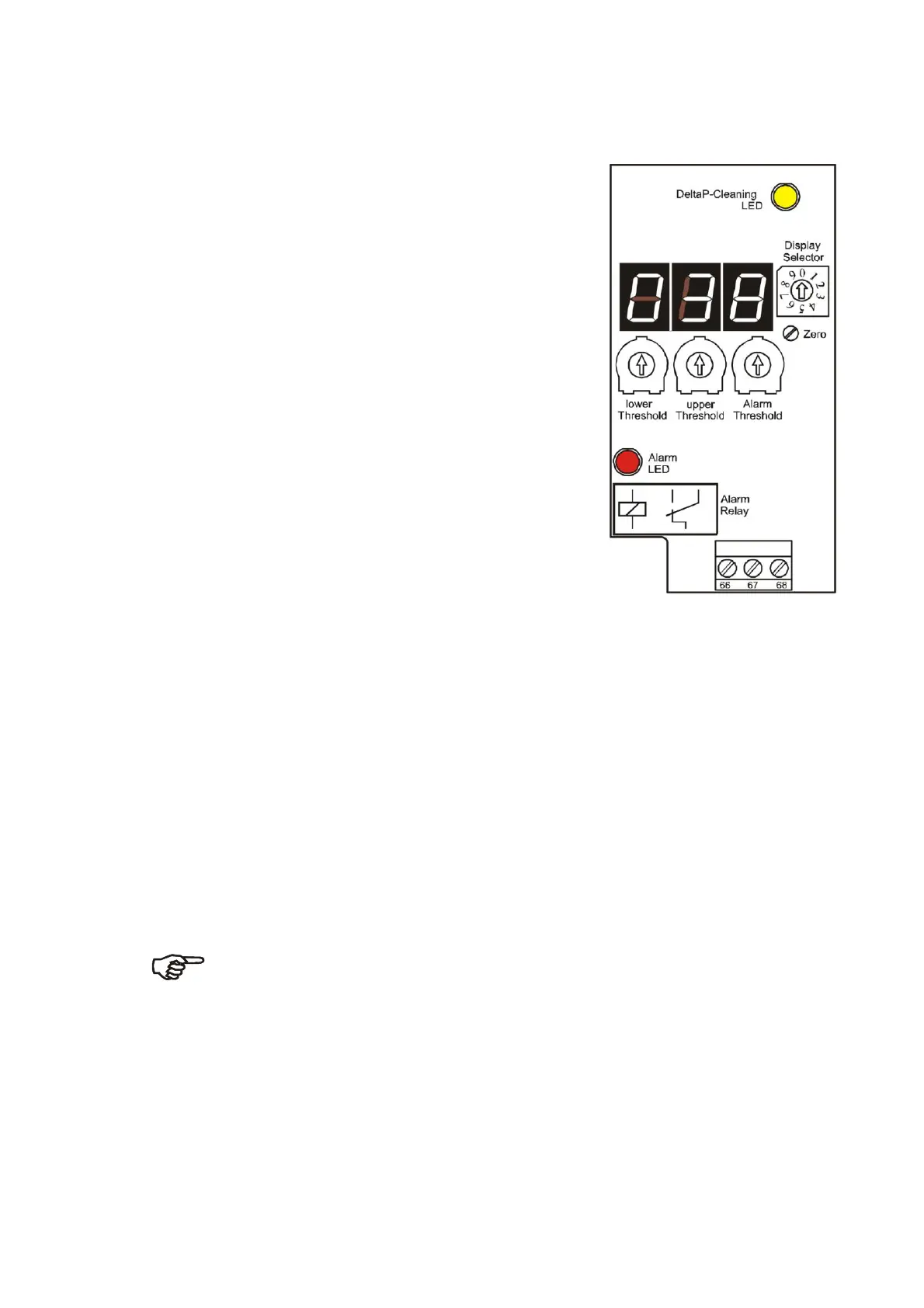
5.1 Operating and Display Elements
●
LED-displays: 3-digit seven-segment display for current
differential pressure or switching thresholds
1 LED for
P-Alarm (red),
1 LED for cleaning (yellow)
●
Display selection: Rotary switch
0* =
p-actual value [mbar]
1* = Cleaning Stop (Lower threshold) [mbar]
2* = Cleaning Start (Upper threshold) [mbar]
3* = Alarm (Alarm threshold) [mbar]
4* = Post cleaning Start [mbar]
5* = Actual valve or number of the defective valve
flashing at the 1. position :
upper segment = interruption
lower segment = over current
6* = Post cleaning cycles
7* = Amount of valves
8* = Pause time [s]
9* = Pulse time [s]x.xx
(* = Potentiometer in the base board)
●
Potentiometer: Lower threshold (cleaning stop)
If the pressure drops under threshold, cleaning stops.
(Cleaning relay inactiv)
Upper threshold (cleaning start)
If the pressure exceeds threshold, cleaning begins.
(Cleaning relay activ)
Alarm threshold
If the pressure exceeds threshold, an alarm is generated.
(Alarm hysteresis
≤
1% of measuring range)
P- zero (Potentiometer below the board)
With this potentiometer the zero value of the
P- sensor can be adjusted.
Do not adjust the potentiometer without switching the display selector
to that value!
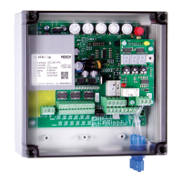
Differential The differential pressure sensor is located below the board (see Page 11).
pressure The connections are suited for hoses with 4 mm inner diameter.
Connection: Left connection (+) :for higher pressure (= pressure before the filter).
Right connection (-) :for lower pressure (= pressure behind the filter).
The pressure inputs are connected to screw fittings (4 mm) at the housing.
 Loading...