EasyManua.ls Logo

Axxeron HESCH HE 5721 - User Manual

Axxeron HESCH HE 5721
24 pages
Print Icon
To Next Page IconTo Next Page
Loading...
Δp-solenoid valve controller
HE 5721
Operating Instructions
(English)
# 371340 | Version 2.1
Question and Answer IconNeed help?

Do you have a question about the Axxeron HESCH HE 5721 and is the answer not in the manual?

Summary

Versions

General Safety Instructions

Device Safety

Details on safe operation and adherence to safety notes for the device.

Unpacking the device

Instructions for checking the contents and condition of the device upon unpacking.

ATEX Explosion Protection

Specific safety instructions for ATEX-approved devices regarding explosion protection.

Mounting

Guidance on proper installation location and conditions for optimal device function.

Electrical Connections and Commissioning

Requirements for electrical wiring, safe commissioning, and initial operation procedures.

Trouble shooting

Initial steps for diagnosing issues before returning the device.

Shut-Down, Maintenance, and Repair

Procedures for safe shutdown, maintenance, repair, and modification guidelines.

Storage and Transport

Recommended conditions for storing and transporting the instrument to maintain its integrity.

ATEX Explosion Protection Details

Detailed information on EX zone 22 suitability, device designation, and precautions.

Troubleshooting and Decommissioning

Steps for troubleshooting faults and safe decommissioning procedures.

Installation Safety Precautions

Specific safety measures for cable glands, unused holes, covers, and cleaning tools.

General Description

System Overview

Overview of the HE 5721 system's purpose and capabilities.

Available Options

Details on optional features such as relays, pressure switch, and extensions.

Installation and Housing

Instrument Dimensions

Specifications and diagram of the physical dimensions of the solenoid valve controller.

Power Supply Requirements

Information on the device's power requirements and voltage compatibility.

Solenoid Valve Controller

Operating and Display Elements

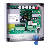
Description of front panel controls, displays, and indicators on the basic and extension boards.

Potentiometer and Jumper Configuration

Explanation of potentiometer functions and Jumper XS1 for device configuration.

Controller Functions

Details on cleaning modes, pause control, and external signal functions.

Inputs and Outputs

Explanation of analog/digital inputs and valve/relay outputs, including specifications.

Core Functions

Detailed explanation of Release/Stop, Start/Ap-IN, and Post-cleaning operational functions.

Malfunction Acknowledgement

How to reset valve error messages and acknowledge malfunctions.

Pressure Switch and Cleaning Cycles

Role of pressure switch for valve monitoring and selection of cleaning cycle types.

Pause Control

How the system performs Δp-dependent pause control using potentiometers and analog signals.

Controller Characteristics

Graphical representation of pause time curves for various differential pressure settings.

System Parameters

Adjustment of System Parameters

Instructions for adjusting system parameters like Cleaning Stop, Cleaning Start, Alarm, etc., during operation.

Parameter Table and Diagram

A table listing system parameters and a diagram illustrating the cleaning cycle relative to differential pressure and time.

Adjusting Aids for Integer Parameters

Explanation of display and valve LED row as aids for setting integer parameters accurately.

Δp-Extension Option

Operating and Display Elements

Overview of the 3-digit display, LEDs, rotary switch, and potentiometers for the Δp-extension.

Differential Pressure Connection

Details on connecting the differential pressure sensor, including port descriptions and hose compatibility.

Outputs

Describes the relay output for Δp-alarm, including its contact rating and terminal connections.

Δp-Adjustment

Procedure for setting the zero point of the Δp sensor using a potentiometer.

Connecting Diagramm

Technical Data

Valve Controller Specifications

Technical specifications for the valve controller, including inputs, outputs, display, functions, and settings.

Δp-Controller Specifications

Technical specifications for the Δp-controller option, including measuring ranges and sensor details.

Δp-Controller Details

Detailed specs for Δp-controller display, ranges, sensor, outputs, and connections.

General Technical Data

Comprehensive technical data including mains supply, fuse, power consumption, temperature, and explosion protection.

Overview

This document describes the HE 5721 Δp-solenoid valve controller, a device designed for pulse activation of solenoid valves in air pollution control systems.

Function Description

The HE 5721 is a control system primarily used for the pulse activation of solenoid valves in air pollution control systems. It offers various controlling and monitoring functions and can be extended with a differential pressure measuring and control system. Cleaning operations can be time-controlled or based on differential pressure with switching thresholds or pause time control. The device monitors valves for open or short-circuits. Optionally, a pressure switch can be used to mechanically check valve function. The Δp extension unit allows for checking a maximum differential pressure.

Important Technical Specifications

Valve Controller:

  • Inputs:
    • Start- / Δp-input: 0(4)-20 mA
    • Release: Contact closed / stop: Contact open
    • Post-cleaning: Impulse signal
    • Malfunction acknowledgement: Impulse signal
    • Pressure switch: For mechanical valve function monitoring
  • Valve Outputs: Max. 12, with an extension up to 24 valves.
  • Valve Voltage: 24 VDC ± 10%
  • Valve Current: 1 A (at pulse time ≤ 1 s and pause time ≤ pulse time), otherwise 0.5 A.
  • Nominal Rating Valve Output: Max. 24 watt.
  • Display:
    • 12 (or 24 with extension) LEDs for valve activation
    • 1 LED "operation" (green)
    • 1 LED "malfunction" (red)
    • 1 LED "cleaning" (yellow)
  • Functions:
    • Partial / complete cycle
    • Δp-dependent control
    • Valve current monitoring (short-circuit / open circuit)
    • Mechanical valve function monitoring (Option)
  • Test Functions: 1 button for valve function test.
  • Relay Outputs (Option):
    • Contact rating: 250 VAC / 5 A
    • 1 change-over contact for operation-/malfunction-indication (fail-safe-circuit)
    • 1 NO-contact for cleaning indication
  • Settings:
    • Number of valves: 1...12 (24)
    • Pulse time: 0.02...1.2 s
    • Pause time: 1...270 s
    • Post-cleaning: 1...12 cycles
    • Post-cleaning start threshold: 0...100% of measuring range

Δp-Controller (Option):

  • Measuring Ranges: 0...25 / 0...500 mbar
  • Δp-Sensor:
    • Max. static pressure: 1000 mbar
    • Linearity: ±1%
    • Hysteresis: ±0.1%
    • Temperature hysteresis: ± 0.5%
    • Temperature drift / zero point: ± 0.025%/K
    • Temperature drift / full-span value: ± 0.01 %/K
  • Settings:
    • Threshold 'cleaning stop'
    • Threshold 'cleaning start'
    • Threshold 'Δp-alarm'
    • Δp-zero-point
  • Analog Output: 0(4)...20 mA (Terminals 23, 24 on the base plane)
  • Relay Output: 1 switched output (change over) for Δp-alarm, contact rating 250 VAC, 5A.
  • Pressure Connections: Tube screw fitting type: DN 4.

General Technical Data:

  • Mains Supply: 100-240 VAC ± 10%, 50 – 60 Hz (option: 24 VDC)
  • Mains Fuse: 0.315 A slow action, type 'TR5' (0.63 A, 3.15 A)
  • Power Consumption: 30 VA (30 VA, 42 W)
  • Electrical Connections: Screw terminal strips: 2.5 mm², Valve connections: 1.0 mm²
  • Operating Temperature: -20 °C...+50 °C (in EX zone 22: -20 °C...+40 °C)
  • Interference Resistance: DIN EN 50081 part 1, DIN EN 50082 part 2
  • Explosion Protection: II 3D Ex tc IIIC T135°C Dc IP65, zone 22 (for ATEX-approved devices)
  • Class of Protection: IP 65
  • Dimensions: 180 x 180 x 85 mm (W x H x D)
  • Housing: Dust tight Makrolon housing (IP65) with metrical threads M20 x 1.5 and 2x M32 x 1.5 for metrical cable glands. Holes are to be sealed with dust tight caps (IP65), 1 sealing cap M32 included.
  • Connecting Kit (Option) 12 valves: 1 cable gland M20, 2 cable gland M32 with multi core insert and sealing bolts.
  • Cable Connection (Option) 12 valves: 1 cable gland M20, 1 cable gland M32 with wire designation and wire end sleeves.
  • Cable Connection (Option) 24 valves: 1 cable gland M20, 1 cable gland M32 with wire designation and wire end sleeves.

Usage Features

  • Operating and Display Elements:
    • Potentiometers: Time setting potentiometers have a logarithmic scale division for pulse time (0.02...1.2 s), pause time (1...270 s), number of valves (1...12 or 12+1...12 with extension board), and post-cleaning start (0...100% of Δp-value measuring range).
    • Jumper XS1: Configures pressure switch (No/Yes), analog input (0...20 mA/4-20 mA), type of cleaning (Threshold/Pause control), and cleaning cycle (Partial cycle/Total cycle). Changes require a device restart.
    • Push-button S1 ('Test'): Initiates cleaning with the next valve, terminates the current valve's pause. If 'total cycle' is selected, cleaning continues to the last valve.
    • LED-indicators: Green for operation, red for malfunction, yellow for cleaning, and red pulse indication for each valve.
    • Valve Error Indication: A flashing valve LED indicates short-circuit, breakage, or mechanical valve function error (with pressure switch).
  • Inputs:
    • Analog Input: 0(4)-20 mA signal for start or Δp-input, measured between terminal 17+ and 18- (GND). Terminal 16 can provide an auxiliary current source (25 mA). In timer mode, terminals 16 and 17 are connected.
    • Digital Inputs: Release (contact closed)/Stop (contact open), Post-cleaning (signal from push-button), Malfunction acknowledgement (signal from push-button), Pressure switch for mechanical valve function checking. Inputs are active when switched to ground (terminal 18 GND).
  • Outputs:
    • Valves: 1...12 (extensible to 24) with 24 VDC / 1A. Outputs have common potential and are switched.
    • Relays: Contact rating 250 VAC / 5 A. One change-over contact for operating/malfunction message (fail-safe-circuit), one normally open contact for cleaning message.
    • Δp-Extension Outputs: One change-over contact for Δp-alarm (250 V AC / 5 A).
  • Functions:
    • Release/Stop: Input releases valve activation; opening the contact stops cleaning.
    • Start / Δp-IN: Two operating modes selected by Jumper XS1 'Type of cleaning':
      • Switching Threshold: Cleaning occurs when a switching contact is closed (e.g., between upper and lower thresholds of a Δp controller).
      • Control: Cleaning occurs permanently with variable pause times (pause control).
      • Analog input signal for cleaning can be internal (from Δp extension board) or external (0(4)-20 mA signal at terminals 17+ and 18-). Higher signal has priority.
    • Post-cleaning:
      • Starts if differential pressure falls below the 'Post-cleaning Start' threshold (adjusted by potentiometer). Number of complete cleaning cycles adjusted by 'Cycles' potentiometer (Jumper XS1=Schw). Pulse and pause times as adjusted.
      • Impulse signal at 'Post-cleaning' input (18,20) triggers post-cleaning.
      • If 'pause control' (XS1 'Regl') is selected, post-cleaning uses a fixed pause time of 30 sec.
    • Malfunction Acknowledgement: Signal at 'malfunction acknowledgement' input resets valve error message (LED and relay). Error message automatically removed when cause is eliminated.
    • Pressure Switch: Input 'pressure switch' checks valve function. Contact must be closed before activating a valve, open during pause time, and close again after pause time. Jumper XS1 must be set to 'with pressure switch'.
    • Cleaning Cycle: Selected with Jumper XS1 'Cleaning cycle':
      • 'Partial cycle': Cleaning continues as long as the start signal is active.
      • 'Total cycle': Cleaning always executes up to the last valve.
    • Pause Control: Δp-dependent pause control selected with Jumper XS1 'Regl'. Operator selects controller characteristic with pause potentiometer. Current differential pressure (internal or external 0(4)-20 mA) signals to the control system. Pause time shortens with increasing differential pressure and prolongs with decreasing differential pressure. Cleaning terminates when differential pressure falls below approx. 5% of measuring range.

Maintenance Features

  • Unpacking: Check for damage during transport and storage. Do not operate if visibly damaged. Observe safety measures for electrostatic discharge.
  • Installation: Install in dust-free, dry rooms, within permissible ambient temperature (50°C), protected from direct solar radiation. Electrical connections must conform to local standards. Power relays in control cabinet should be interference-suppressed.
  • Commissioning: Ensure supply voltage matches specifications. All covers must be applied. Check for impact on other connected equipment. Protective earth must be connected for protection class I instruments. Operate only when mounted in enclosure.
  • Operation: Switch on supply voltage. Allow approx. 15 min warm-up time.
  • Troubleshooting: Check other equipment and connections first. If issues persist, return to manufacturer. Note that primary elements (e.g., thermocouples) connected to energized transmitters may reduce insulation resistance, making additional earth connection impermissible.
  • Shut-Down: Disconnect from all voltage sources and protect against accidental operation. Check for impact on other connected equipment.
  • Maintenance, Repair, Modification: No particular maintenance required. Electro-mechanical relays have limited durability. Only trained, authorized personnel may perform modifications, maintenance, and repair. Unauthorized repairs void the guarantee. If a fuse blows, determine and remove the cause; replace only with fuses of the same type and current rating.
  • Explosion Protection (for ATEX-approved devices): Suitable for EX zone 22 with lid closed. Evacuate explosive atmospheres before opening for parametrization.
  • Storage: Store in dry, dust-free, vibration-free rooms at -20°C...+70°C. Avoid direct UV-radiation.
  • Transport: Packing material should prevent damage from an 80 cm drop. Transport temperature: -40°C...+85°C.
  • Cleaning: Only wet or moistened cleaning tools are allowed for the plastic housing to prevent electrostatic charges.
  • Δp-Adjustment: Adjust the 0-point potentiometer (below the board) only when no differential pressure is present (no measuring hoses connected). For better accuracy, check the current output 0(4) to 20 mA at terminals 23+ and 24-. Adjustment should be carried out at operational temperature as the sensor can have a temperature drift of up to ± 1 mbar. Do not adjust the potentiometer without switching the display selector to that value.
  • Adjusting aids for Integer Parameters: The instrument offers two aids for setting integer values with potentiometers:
    1. Display shows values like -1, 1, 1-2, 2, 2-3, 3, 3-4, 4 etc. The value is correctly adjusted if no dash is shown.
    2. Valve LED row: Cycle adjustment (LED line flashes or lights up) and Valve adjustment (max. 2 individual LEDs flash or light up). During adjustment, the cleaning process is not interrupted, and the cleaning pulse is displayed. Valve error representation is suppressed.

Axxeron HESCH HE 5721 Specifications

General IconGeneral
BrandAxxeron
ModelHESCH HE 5721
CategoryController
LanguageEnglish