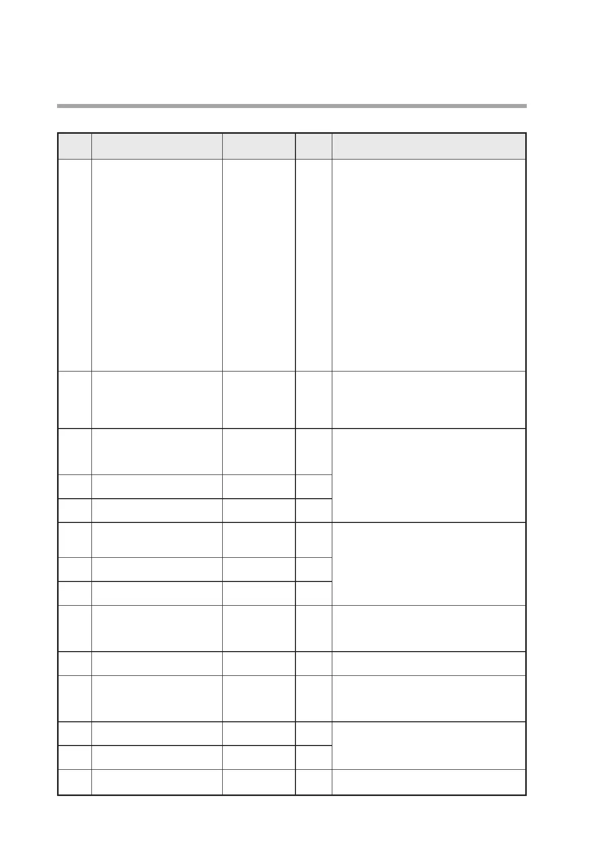
● Parameter settings
Item Name Setting range
Factory
Description
setting
AO.20 Flow rate assignment for 20 mA 0 to 400 %FS
Depends
• No decimal point is displayed on RS-485
analog output
*1
equiv.
*5
on model
communications models.
number
• Factory settings are shown below.
MCF0080
→ 200
MCF0150
→ 500
MCF0151
→ 1000
MCF0250
→ 3000
MCF0400
→ 6000
MCF0500
→ 12000
• The decimal point is not shown in the setting
range. Depending on the model number the
decimal point is added to the display.
• If the setting is less than 10 % of the FS
flow rate, the desired output may not be
possible. Also, if the setting is zero, when
there is an alarm the output will be fixed
(unchanging).
• If the flow rate units are changed in function
setup C02, set Ao20 again.
AO.04 Flow rate assignment for 4 mA 0 to 400 %FS 0 • No decimal point is displayed on RS-485
analog output
*1
equiv.
*5
communications models.
• The decimal point is not shown in the setting
range. Depending on the model number the
decimal point is added to the display.
E 1.SP Event 1 instantaneous flow rate 0 to 400 %FS 0 • Setup is enabled when function setup C03 is
*2
equiv.
*5
set to 01to 06.
• The decimal point is not shown in the setting
range. Depending on the model number the
E 1.hyS Hysteresis for event 1
*2
0 to 10 %FS 1 decimal point is added to the display.
(at 1% interval) • If the flow rate units are changed in function
E 1.dLY ON delay for event 1
*3
0 to 60 s 0 setup C02, set E1.dLy again.
(at 1 s interval)
E2.SP Event 2 instantaneous flow 0 to 400 %FS 0 • Setup is enabled when function setup C03 is
rate
*2
equiv.
*5
set to 03 or 06.
• The decimal point is not shown in the setting
E2.hYS Hysteresis for event 2
*2
0 to 10 %FS 1 range. Depending on the model number the
(at 1% interval) decimal point is added to the display.
E2.dly ON delay for event 2
*3
0 to 60 s 0 • If the flow rate units are changed in function
(at 1 s interval) setup C02, set E2.dLy again.
CF. Output correction factor 0.100 to 2.000 1.000 Settable in increments of 0.001. This setting
affects both indication and output. If it is
changed, the peak value and lowest value for
instantaneous flow rate are cleared.
LfcWt Low flow cutoff 1 to 50 %FS 1 This setting applies to both normal flow and
(at 1% interval) reverse flow.
HI .Lt Upper limit for indication 100 to 200 %FS 200 The upper limit for indication can be set at a
lower level than the maximum of 200 %FS. If
the flow exceeds this upper limit, the display will
show only the value specified by this setting.
EI .LO Last 5 digits of integrated flow 00000 to 99990 0 Settable when function setup C03 is set to
(event setup) 07 to 10.
EI .HI First 4 digits of integrated flow 0000 to 9999 0
(event setup)
COSt Flow rate cost multiplier
*4
1.0 to 100.0 100.0 This setting is used to indicate cost in the
device information display.
26
Chapter 5. SETTING AND OPERATION