15
AB-7329
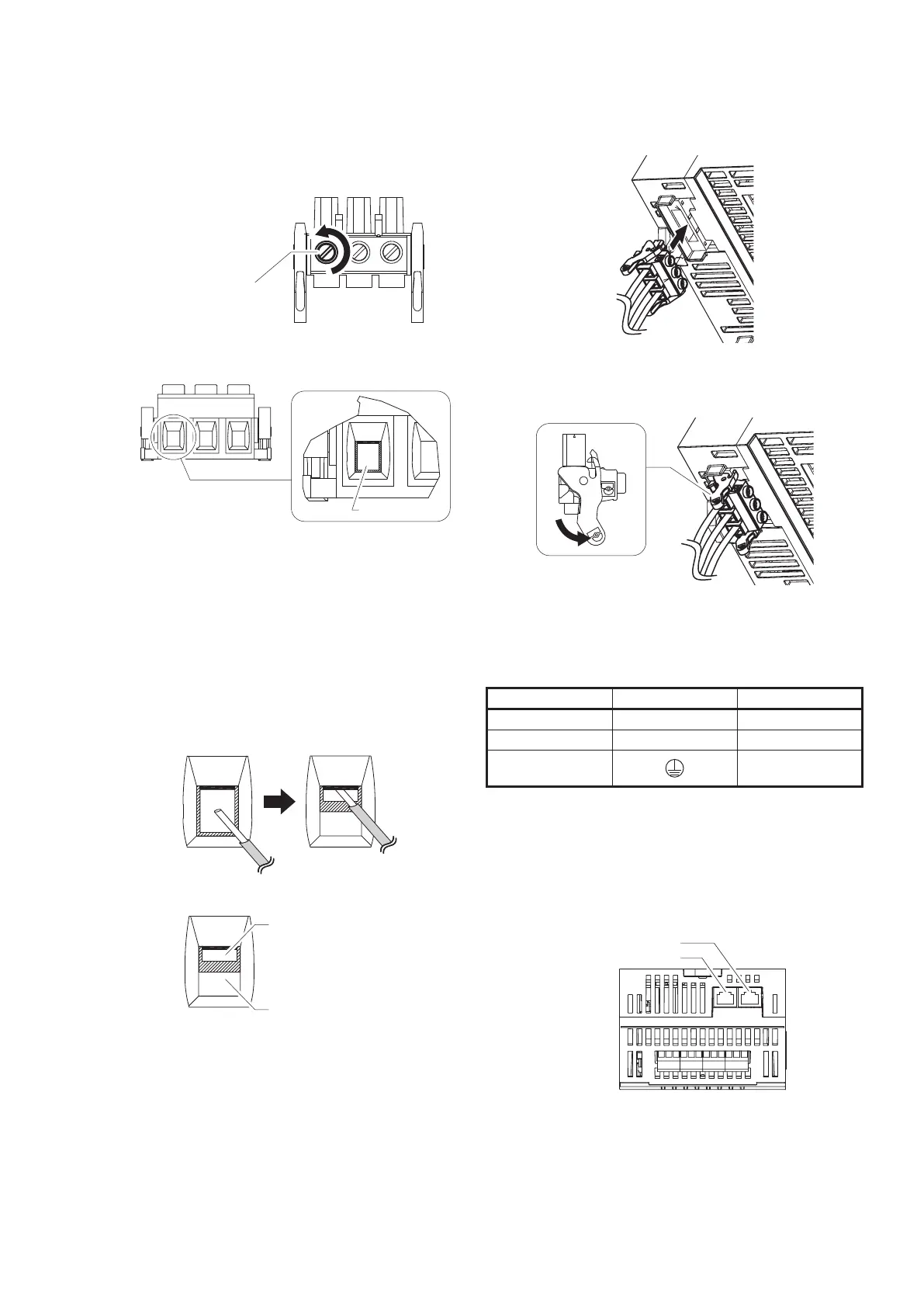
(3) Turn the screw above the cable clamp (the hole for
the wire) of the connector to the left with a screw-
driver to open the cable clamp.
Turn the screw to the
left thoroughly to
open the insertion slot
*
Compatible screwdriver blade: 0.6 × 3.5 mm
Insertion slot
(4) For a daisy chain connection, use and twist the
wires specied in "Specications for Wiring" (limited
to those with the same cross-sectional area ranging
from 1.25 to 1.5 mm
2
).
(5) Insert the wire stripped in step (1) into the cable
clamp and tighten it by turning the screw above the
cable clamp to the right with a screwdriver.
The screw tightening torque is 0.5–0.6 N•m.
Make sure there are no strands of cable wire
protruding from the cable clamp.
Note: Check that the wire is inserted into the cable clamp.
Do not insert
wire here
Cable clamp
(insertion slot)
(6) Lightly pull the wire to check that it does not come
out.
(7) Insert the connector into the device.
Insert
Check that the release levers of the connector are
securely locked.
(8) Lightly pull the wire to check that the power supply
connector does not come out.
<Power Supply Terminals>
Terminal No. Symbol Description
1 L AC input
2 N AC input
3
Protective ground
terminal
z Connecting to the local I/O network
Connect the LAN cables to LAN1 and LAN2.
There are two network topologies, daisy chain and ring,
that can be used to connect the Advanced Remote I/O
Modules.
LAN2:Ethernet
LAN1:Ethernet

 Loading...

