6
J3
CN2
CN1
J1
J2
5
34 2 1
34 2 1
5
EN
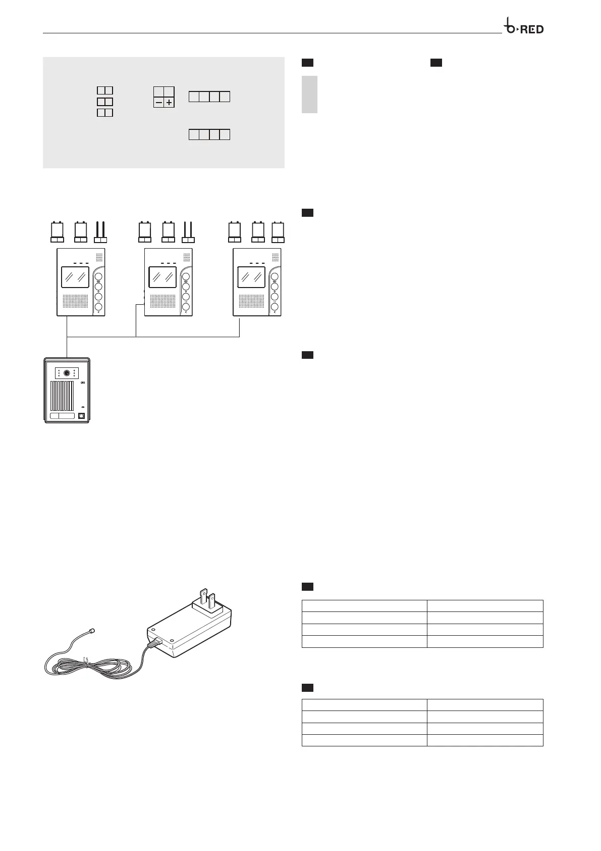
TERMINAL BOARDS
CN1-CN2
1
AUDIO (Red)
2 GND (Blue)
3 V+ (Yellow)
4 VIDEO (White)
5 + POWER (
Red
)
6 – POWER GND (
Black
)
CN1 Connected with Entry Panel 1
CN2 Connected with Entry Panel 2
ES
BORNERAS
AUDIO (
Rojo)
GND (Azul)
V+ (Amarillo)
VIDEO (Blanco)
POWER (Rojo)
POWER GND (
Negro
)
Conectado con a la Placa Exterior 1
Conectado con a la Placa Exterior 2
J3 J1
J2
J3 J1
J2
J3 J1
J2
EN
JUMPER
J3 (Back light compensation for entry panel call button):
The default setting is with J3 jumper connected. Remove the jumper if the
entry panel button back light is not needed.
J1 (Ringing output):
It is normally supplied inserted. When a call from entry panel to indoor
phone is performed the outdoor panel can also hear the call ring. Remove
jumper J1 to avoid that.
J2 (Video signal compensation):
It is normally supplied inserted. When there are more than one internal
receiver, level J2 jumper connected to the furthest one to assure the video
signal transmission. Remove J2 from the other receivers (see figure 4).
ES
JUMPER
J3 (luz de fondo para el botón de llamada del frente de calle):
La configuración predeterminada es con el jumper J3 conectado. Retirar el
jumper si en el frente de calle la luz de fondo del botón no es necesaria.
J1 (Timbre de llamada):
Normalmente se suministra el equipo con el jumper instalado. Cuando se
realiza una llamada desde el frente de calle hacia los receptores interiores,
en el frente de calle también se puede escuchar el tono de llamada. Retirar
el jumper J1 si no lo desea.
J2 (compensación de la señal de vídeo):
Normalmente se suministra el equipo con el jumper instalado. Cuando hay
más de un receptor interno debemos considerar la terminación de señal
para garantizar la impedancia en la señal de video. El jumper J2 del ultimo
receptor conectado asegura la transmisión de la señal de vídeo. Retire J2 de
los otros receptores (figura 4).
VPSK01 US
EN
TECHNICAL FEATURES
Main supply 100-240 VAC, 50-60 Hz, 0,4 A
Nominal power supply 14,5 VDC, 1,3 A
Dimensions 105x58x32 mm
Operating temperature 0 °C +40 °C
ES
CARACTERÍSTICAS TÉCNICAS
Entrada 100-240 VAC, 50-60 Hz, 0,4 A
Salida 14,5 VDC, 1,3 A
Dimensiones 105x58x32 mm
Temperatura de funcionamiento 0 °C +40 °C