VEPK01 US
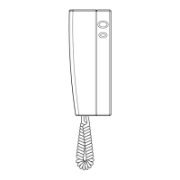
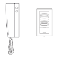
indoor monitor
interior del monitor
door lock
cerradura
1: red/rojo
2: blue/azul
3: yellow/amarillo
4: white/blanco
5: black/negro
EN
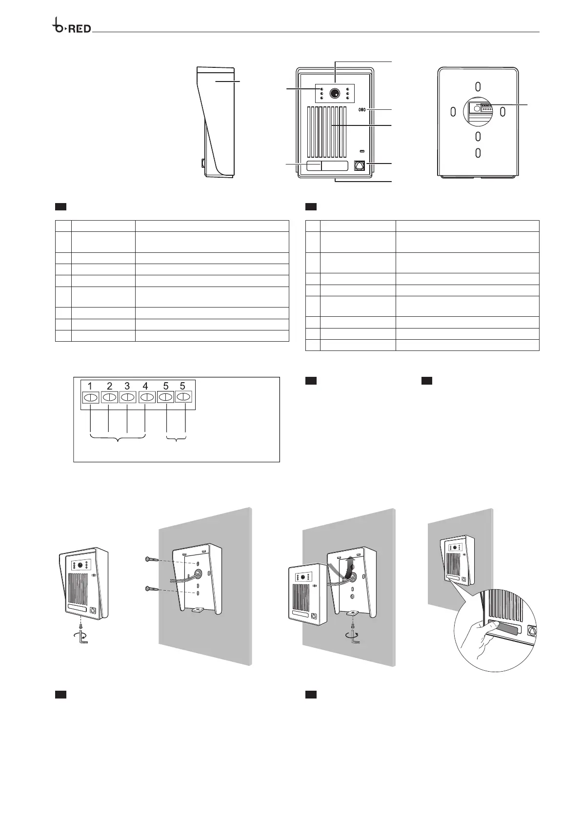
DESCRIPTION
Rain Cover Protect the camera from outside water
LED Assistance
Provided lighting during night time for better
visibility
CCD Camera Capture the image to sent to the monitor
Speaker Audio from the monitor is delivered
Calling Button Call the indoor phone to communicate
Microphone
Delivers and sound voice when communica-
tion with the indoor phone
Screw Hole Fix the rain cover to the unit
Nameplate Show residential name
Connection wiring Connection with the monitor
ES
DESCRIPCIÓN
Cubierta de Lluvia
Protege la cámara del clima /intemperie
LED Luminoso
Provee iluminación durante la noche para una
mejor visibilidad
CCD
Captura la imagen que es enviada a los monito-
res internos
Bocina
Emite el audio recibido desde los monitores internos
Botón de llamada
Realiza la llamada a los recetores internos
Micrófono
Envía el audio de la voz durante la comunicación
al receptor interior
Tornillo de seguridad
Fija la cubierta de lluvia al cuerpo del frente de calle
Placa de identi cación
Indica el numero o nombre de la residencia
Terminal de conexión
Terminales de conexión al monitor
indoor monitor
interior del monitor
door lock
cerradura
1: red/rojo
2: blue/azul
3: yellow/amarillo
4: white/blanco
5: black/negro
EN
INSTALLATION
Unscrew the blocking screw and remove the rain cover from the unit (figure 1).
Use the rain cover to mark the location point accurately. Drill the holes and
use the screw anchors to fill them.
Fasten the rain cover to the wall using the provided screws (figure 2).
According to the wiring diagram, perform the wiring connections (figure 2).
Mount the unit to the rain cover and fasten the blocking screw (figure 3).
To write the user name, remove the nameplate as shown in (figure 4).
ES
INSTALACIÓN
Desatornillar el tornillo de seguridad y retirar la cubierta de lluvia (figura-1)
Utiliza la cubierta de lluvia para marcar la ubicación del frente de calle, tala-
dre los agujeros y utilice los taquetes para llenarlos
Fije la cubierta de lluvia en la pared utilizando los tornillos suministrados
(figura 2). De acuerdo con el diagrama de cableado, realice las conexiones
de cableado (Figura 2). Monte la unidad del frente de calle a la cubierta para
lluvia y apriete el tornillo de seguridad (figura 3). Para escribir el nombre de
usuario, quitar la etiqueta como se muestra en (figura 4).
6
EN
TERMINAL BOARDS
ES
BORNERAS
1
AUDIO (Red) AUDIO (
Rojo)
2 GND (Blue) GND (Azul)
3 V+ (Yellow) V+ (Amarillo)
4 VIDEO (White) VIDEO (Blanco)
5
Contact solenoid lock relay Contacto relé de cerradura electrónica
5