WWW.BALTIMOREAIRCOIL.COM
12
See Note 10
Pipe Support Location
See Figure 18, Detail A
C (Typ. Per
Cell)
Water Inlet
(See Unit Print For Size)
See Figure 18, Detail C
Pipe Support Location
See Figure 18, Detail A
See Note 5
Plan View
Elevation View
Static Lift
B
A
A A
22
H
H
HHH
2
2
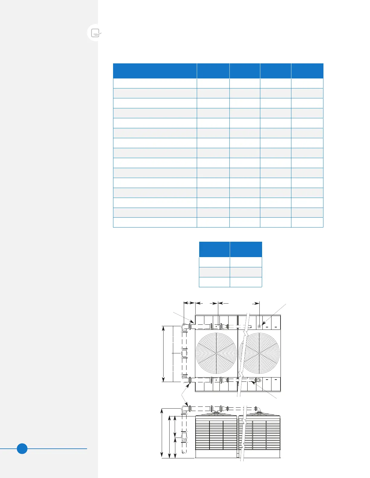
Top Inlet Piping Installation
Use the following drawings, notes, and tables when installing top inlet piping.
Drawings shown are for multi-cell installations. For single cell installations, simply
ignore the additional cells and dimension “C” from Table 4.
Figure 16. Single Riser Piping Schematic
Table 4. Dimensions for Series 3000 Piping Schematic
Model Number A B C H
S3E/XES3E-8518-05x 10’-6 3/4" 4’-2 7/8" 8’-8 1/4" 8’-7 3/4"
S3E/XES3E-8518-06x 10’-6 3/4" 4’-2 7/8" 8’-8 1/4" 9’-11 3/4"
S3E/XES3E-8518-07x 10’-6 3/4" 4’-2 7/8" 8’-8 1/4" 11'-3 3/4"
S3E/XES3E-1020-06x 12’-6 3/4" 4’-10 5/8" 9’-11 3/4" 9’-11 3/4"
S3E/XES3E-1020-07x 12’-6 3/4" 4’-10 5/8" 9’-11 3/4" 11’-3 3/4"
S3E/XES3E-1222-06x 14’-0 3/4" 5’-10 7/8" 12’-0 1/4" 9’-11 3/4"
S3E/XES3E-1222-07x 14’-0 3/4" 5’-10 7/8" 12’-0 1/4" 11’-3 3/4"
S3E/XES3E-1222-10x 14’-0 3/4" 5’-10 7/8" 12’-0 1/4" 15’-5 1/2"
S3E/XES3E-1222-12x 14’-0 3/4" 5’-10 7/8" 12’-0 1/4" 18’-1 1/2"
S3E/XES3E-1222-13x 14’-0 3/4" 5’-10 7/8" 12’-0 1/4" 19'-5 3/4"
S3E/XES3E-1222-14x 14’-0 3/4" 5’-10 7/8" 12’-0 1/4" 20’-9 1/2"
S3E/XES3E-1424-07x 16’-6 3/4" 6’-11 9/16" 14’-1 5/8" 11’-3 3/4"
S3E/XES3E-1424-12x 16’-6 3/4" 6’-11 9/16" 14’-1 5/8" 18’-1 1/2"
S3E/XES3E-1424-13x 16’-6 3/4" 6’-11 9/16" 14’-1 5/8" 19'-5 3/4"
S3E/XES3E-1424-14x 16’-6 3/4" 6’-11 9/16" 14’-1 5/8" 20’-9 1/2"
Table 5. Flow Control Valve
NOTES FOR FIGURE 16:
1. All piping shown by dashed
lines is to be furnished by
others. Refer to the certified
unit print for details on the
cooling tower.
2. Field piping should be
fabricated at the time of unit
installation. Pre-fabrication of
pipe work is not recommended.
3. Required static pumping head
from base of cooling tower
is indicated by static lift
dimension and piping friction
losses.
4. When tower is equipped with
safety railing package, inlet
piping should be designed to
clear the railing. Adjust static
lift as required.
5. For units installed on vibration
isolation rails (provided by
others), flexible connections
should be installed in the
piping just before the tower
perimeter.
6. All piping supports to be
designed, furnished, and
installed by others.
7. Supply piping to cooling
tower inlet connections may
be supported from the tower
structure only at the pipe
support locations shown. Piping
must not be supported by the
tower inlet connections. Piping
outside the perimeter of the
tower must not be supported
from the tower.
8. Supply piping supports must be
designed to rest on the walls
of the hot water distribution
basins at locations indicated
(see Figure 18, Detail A).
9. Maximum diameter of inlet
header piping that can be
supported by the cooling tower
distribution basins is 14”.
10. Provide adequate space
between cooling tower and riser
piping to allow for entry into the
cooling tower access doors.
Size Width
6” 2 1/4”
8” 2 1/2”
10” 2 13/16”
 Loading...