Instructions 67-9319 Bacharach, Inc. Page 2-5
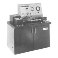
INJECTOR CALIBRATOR CD3 INSTALLATION
Figure 2-12. Initial Checks - Air Pressure
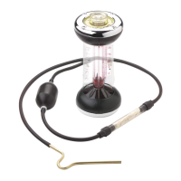
Figure 2-13. Initial Checks - Calibration Fluid
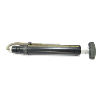
Figure 2-14. Initial Checks - Cambox Oil
CONDITION YES NO
_______________________________________________
3. The air line from the shop air _____ _____
supply is connected to the AIR
inlet at the back of the calibrator.
4. The cold water line is connected_____ _____
to the WATER IN port.
5. The drain line is connected to _____ _____
the WATER OUT port.
NOTE: Do not connect any valve,
shutoff, or other restriction in
the drain line.
6. Inlet Air Pressure Regulator _____ _____
gauge. (Inside lower rear
panel) indicates 90 ± 5 psi.
Secondary Air Pressure
Regulator must read 60 psi
(4.1 bar) +5 -0 psi. Reset if
necessary.
NOTE: Air pressure regulators
were set at the factory.
7. Both drain valves are closed on_____ _____
the calibration fluid reservoir.
8. The calibration fluid reservoir _____ _____
is filled to the “F” mark on the
dipstick. Use Calibration Fluid
P.N. 67-5598 (SAE J967).
9. The cambox is filled with oil _____ _____
to 3-3/4 inch from the top of
cam box. If additional oil is
required, use SAE 30W motor
oil (non-detergent).
*If electrical power does not correspond to the data
on the nameplate, consult the Bacharach factory.
(Checklist continued on next page)
Secondary
7 Reservoir
Drain Valves
6 Air Pressure
Re
ulator Gau
es
Primary
8 D i p s t i c k
9 C a m b o x O i l
 Loading...