Multi-Zone Gas Monitors
P/N: 3015-5074 Rev 11 57
Parameter Description
Default is 1. Can be set for 2 via System data register.
Maximum Response Time
4000 ms when directly accessing the MZ monitor.
8,000 ms when accessing the MZ monitor through the RD.
CRC per MODBUS specifications
NOTE: All data sent out from the MZ is in “little endian” byte order (Least significant byte
followed by most significant byte). This should be taken into account if the master that
process the data is a “big endian” type. Non-data information (starting address, number of
points, etc.) follows normal MODBUS protocol, which is Big Endian.
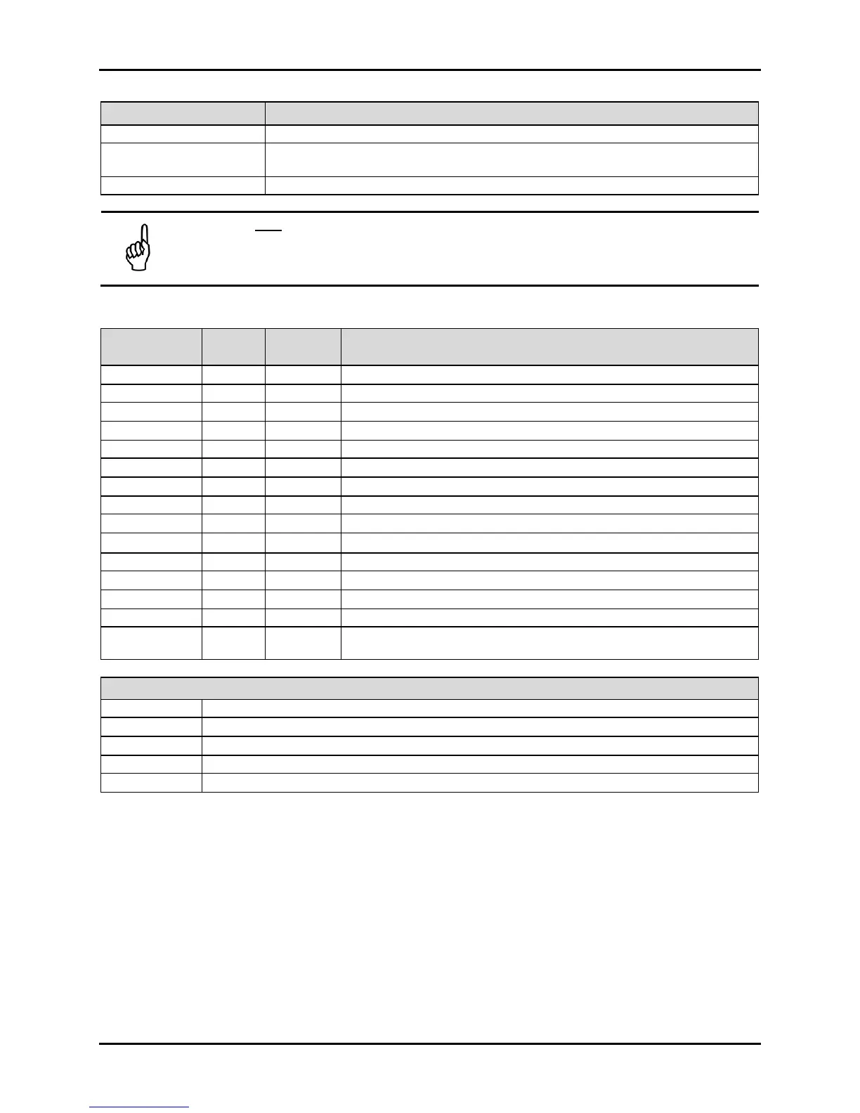
B.3.6. Summary of Registers
Register
Name Number
HEX Decimal Description
Status 0x0011 17 R/W Operating summary of faults, alarms and status
R/W Setup data for up to 16 zones (xx defines zone number)
CAL Data 0x0014 20 R/W Cal Factors for all gases
R Raw measurement of sensors
W Release MZ out of hold mode
R 20 most recent fault events (xx = 00 or 01)
R 20 most recent flow fault events
R 20 most recent alarm events (xx = 00, 01, or 02)
W Puts MZ into service mode
W Releas e MZ from service mode
R PPM values for all zones
Zone Log 0x3yxx 0-6
Trend data for each MZ zone [y = zone # (starting at 0), xx = 00 – 06]
Data
Data Type Abbreviations