Multi-Zone Gas Monitors
58 P/N: 3015-5074 Rev 11
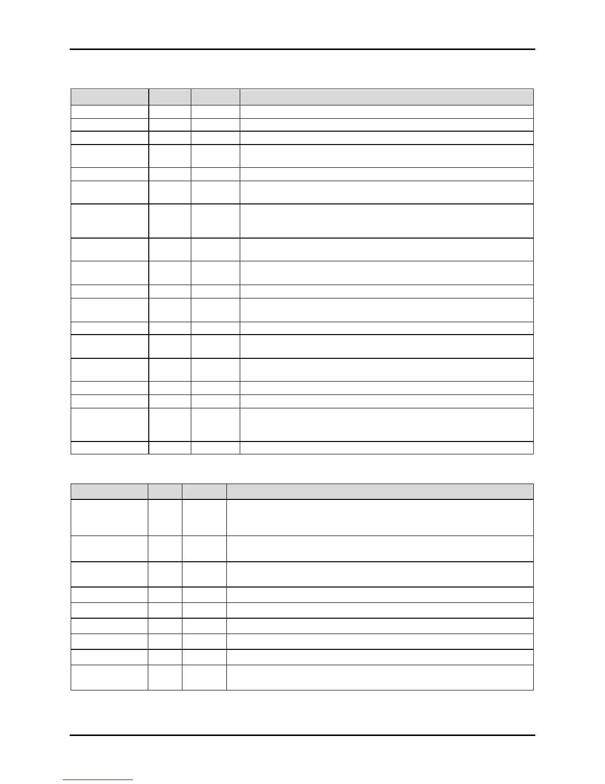
B.3.7. System Data Register 0x0010 (16 Dec) (R/W, 54 Bytes)
Variable Type Length Description
Indicates EEPROM has been initialized if value = 300 DO NOT MODIFY
Firmware Rev Level DO NOT MODIFY
Firmware Serial Number DO NOT MODIFY
Node UC 1 byte
Network Slave Node # (valid values are 1-15). The default is that
indicated by the Node DIP Switch on main board.
Array defining text name of unit
Stop_Bits C 1 byte
Number of stop bits used in the MZ data stream. Default = 1. Other
available value is 2
Aud_Alarm UC 1 byte
Sounds internal board buzzer on condition; 0 = no buzzer; 1= Alarm;
2=Fault; 3=Leak; 4=Spill; 5=Evacuate; 6=Monitor Off line (DEFAULT =
0)
Mode
UC 1 byte
Defines Alarm Operation. Manual Acknowledge = 0; Auto Acknowledge
= 1 (DEFAULT = 0)
Num_Zones UC 1 byte
Number of install zones (Value initialized during auto detect during
Power On Self Test).
UNUSED TIM 13 bytes UNUSED
Rezero_Mode UC 1 byte
Defines re-zero mode. Auto Re-zero = 0; Re-zero every zone = 1
(DEFAULT = 0)
Length of zone hold interval in minutes (DEFAULT = 15 minutes)
UNUSED UC 1 byte
Minim um detection limit (in PPM).
Concentrations less than or equal this
value will read as 0 PPM (DEFAULT = 0 PPM)
Avg_Size UC 1 byte
Size of running average used in computing PPM value. DO NOT
MODIFY.
Defines PPM current loop output. (DEFAULT = 0.16 mA/PPM)
Serv_Mode_TO UI 2 bytes Service Mode Timeout value (in minutes). (DEFAULT = 60 MINUTES)
RS485_BAUD UI 2 bytes
BAUD RATE for RS-485 connection (between RD and MZ monitor or
MODBUS master and MZ depending on the Network topology).
Default=9 (19.2K); other values are 8=9600, 7=4800
B.3.8. Status Register 0x011 (17 Dec) (R/W, 10 Byte s)
Variable Type Length Description
Mode UC 1 byte
Defines Operating Mode of MZ. 0 = normal Mode; 1 = Zone_Hold Mode; 2
= Diagnostic Mode; 3 = Service mode. DO NOT MODIFY (use zone hold
register or service mode register to change this parameter)
State UC 1 byte
Defines MZ Current State. 0 = Idle; 1 = Sampling; 2 = Zeroing; 3 = Warm
Up, 4 = Pressure Check DO NOT MODIFY
Measuring UC 1 byte
Value = 1 if unit is acquiring detector signal for running avg. DO NOT
MODIFY
Active_Zone UC 1 byte Current Zone being checked. 0=zone 1, 1=zone 2, etc.
Ma x _ Alarm UC 1 byte Indicates highest non-acknowledged alarm level DO NOT MODIFY
Alarm_Count UC 1 byte Number of alarms that are currently active. DO NOT MODIFY
UNUSED UC 1 byte UNUSED
Loop_Card UC 1 byte Value = 1 if 4-20 mA card has been detected. DO NOT MODIFY
Fault UI 2 bytes
Fault Flag Structure uses bitwise access to 16 bit word as defined in the
table below.