B
MAINTENANCE
Read all of SAFETY and this section before attempting any procedure. Pay particular attention to Notices, Cautions, Warnings and Dangers.
33
Owner’s Manual
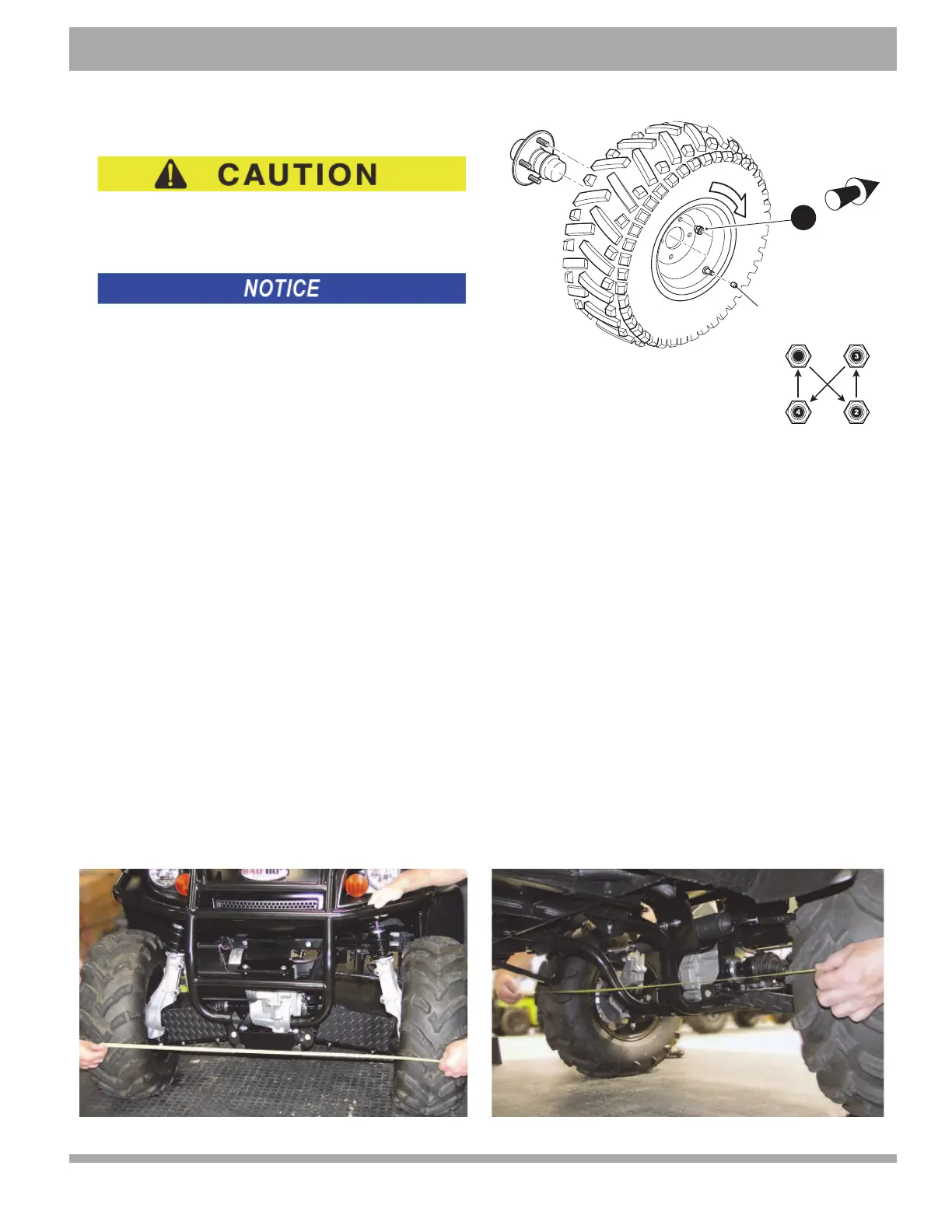
Wheel Installation
To reduce the possibility of component damage, do not
tighten lug nuts to more than 85 ft. lbs. (115 Nm) torque.
It is important to follow the ‘cross sequence’ pattern when
in
stalling lug nuts. This will assure even seating of the wheel
against the hub.
With the valve stem to the outside, mou
nt the wheel onto the
hub with lug nuts. Finger tighten the lug nuts (1) in a ‘cross
sequence’ pattern. Tighten the lug nuts to 50 to 85 ft. lbs. (68
to 115 Nm) torque in 20 ft. lbs. (27 Nm) increments following
the ‘cross sequence’ pattern.
Unidirectional Tires
Unidirectional tires may be identified by a directional arrow on the sidewall. Be sure to position the wheel on the hub cor-
rectly with the arrow indicating the direction of rotation when moving forward.
WHEEL ALIGNMENT
Driving over rough terrain may cause misalignment of the wheels. With four wheel independent suspension both front
and rear wheels may need to be aligned.
Wheel Alignment
Tool List Qty. Tool List Qty.
Tape Measure.............................................................. 1 Open End Wrench, 12 mm...............................
........... 1
Open End Wrench, 17 mm.......................................... 1 Open End Wrench, 19 mm..........................................
1
Park the vehicle on a level surface, set the
front wheels straight ahead. Turn the key switch to OFF, remove the key from
switch and set the park brake.
With vehicle empty (no passengers or payload), measure distance be
tween center of both the front and the rear sets of
tires. Measure both in front and behind each tire set, keeping tape measure parallel to the ground. The measurement
behind the tires should be 1/8” more than the measurement taken at the front of the tires to produce a toe-in condition.
1
R
o
t
a
t
i
o
n
Valve Stem Cap
Cross Sequence
Tire style may vary
1
Front of
Vehicle

 Loading...