Page 5 56016-01_97_A
G
ED AC
BLK AC
32
6
62
WIT
HBANK A
1
66
65
1
16
2
6
6
33
3
36
37
35
ALBOA INSTRUMENTS
INC
VS500Z
/N 22972 REV
MADE IN U.S.A
PYRI
HT 2005
8
44
60
2
4
TR
10
100
TB1
FUSE .3A 250V
FU
E 20A 250
F
E 3A 250V
D
LA
FU
E 30A
23
74
7
29
4
50
17/2
20
1
10
13
2
T
L
T
X. F
EN. A
EN.
VA
2
3
F
12
4
2-SPD
XT RL
1
R
UE
RAN
E
FOR TB1:
7-30 IN. LBS
HO
LAC
EUTRAL
HO
G
VS5xxD mode
Blower
7
X-P332
N 5513
P
N 22909 REV
2-Spd P2
5.5 kW
Heater rated @ 240V
(Approx. 1.4kW @ 120V)
Audio VisualAudio Visual
Circ.Pump
Ozone
Ozone and Circ Pump must be same voltage.
Do not remove Fuse F7 (20A)
12V
Light
2-Spd P1
PCBA Rev D & E only.
Black jumper required.
Do not remove.
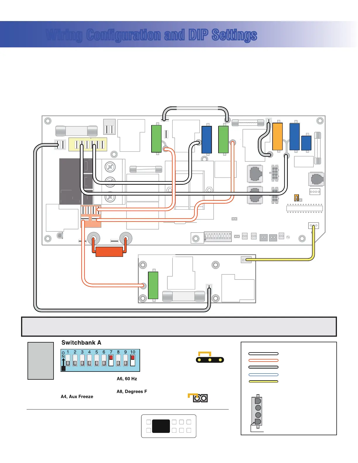
Wiring Configuration and DIP Settings
Setup 1 (As Manufactured)
s 60UMP3PEED
s 60UMP3PEED
s 6"LOWER
s 6/ZONE
s 63PA,IGHT
s 6!<6(Stereo)
s 6K7(EATER
s 6,$6,$-AIN0ANEL
s 6#IRC0UMPOPTIONAL
A1, Test Mode OFF
A2, See Table 1
A3, N/A
A7, J17/26 Disabled
A10, See Table 1
A9, Non-Circ Mode
A5, 2-speed P1
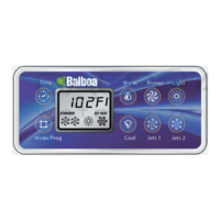
Panel Button Assignments
1=Time
2=Mode/Prog
3=Temp Up
4=Temp Down
5=Light
6=Pump 1
7=Pump 2
8=Unused
Panel Button Positions
1
2
3
4
8
6
5
7
100
94
43
SSID #
VS51x/VS5xxS/VS5xxD
Compatible
J12
123
Memory
Reset
J43
A7, J17/26 Enabled
8=J17/26
120 Volt Connections
240 Volt Connections
Black AC Jumpers
12 Volt Connections
Relay Control Wires
Wiring Color Key
Typically Line voltage
Typically Line voltage for 2-speed pumps
Neutral (Common)
Ground
Note flat sides in connector
Board Connector Key
1
2
3
4
WARNING: Main Power to system should be turned OFF BEFORE adjusting DIP switches.
WARNING: Persistent Memory (J43) must be RESET to allow new DIP switch settings to take effect. (See Persistent Memory page)
 Loading...