Page 6 56016-01_97_A
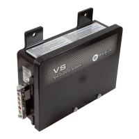
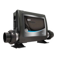
Base Model VS520DZ
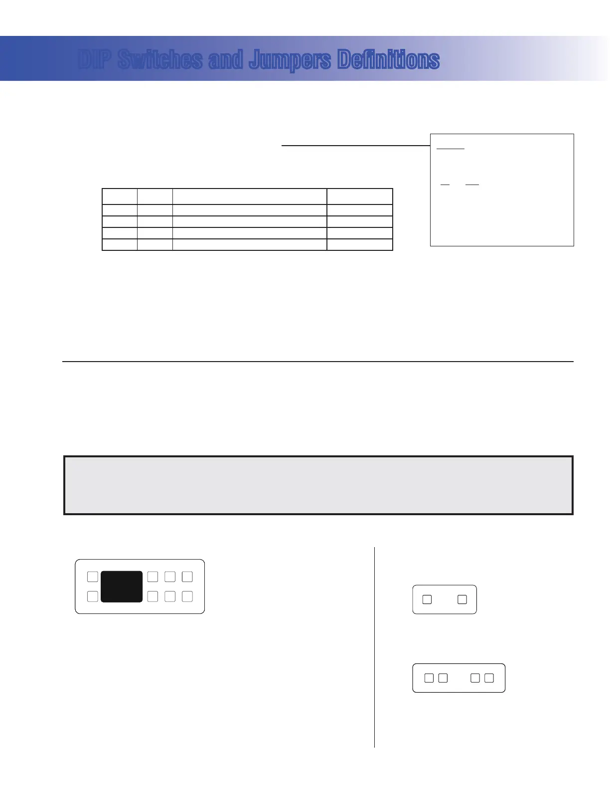
DIP Switches and Jumpers Definitions
DIP Switch Key
A1 Test Mode (normally OFF)
A2+A10
Control amp draw requirements (See Table 1)
A3 N/A (must be OFF)
A4 Aux Freeze (must be OFF)
A5+A9 Pump 1 speeds and Circ Modes:
A5 A9 Circ Mode Pump 1 Speed
OFF OFF Non-circ 2-speed
ON OFF Circ "acts like Pump 1 low" (filters/polls/ect) 1-speed
OFF ON 24 hours with 3°F shut-off 1-speed
ON ON 24 hours with 3°F shut-off 2-speed
A6 “ON” position: 50Hz operation
“OFF” position: 60Hz operation
A7 “ON” position: J17/26 equipment enabled
“OFF” position: J17/26 equipment disabled
A8 “ON” position: temperature is displayed in degrees Celsius
“OFF” position: temperature is displayed in degrees Fahrenheit
SSID 100 94 43
WARNING:
sSetting DIP switches incorrectly may cause abnormal system behavior and/or damage to system components.
sRefer to Switchbank illustration on Wiring Configuration page for correct settings for this system.
sContact Balboa if you require additional configuration pages added to this tech sheet.
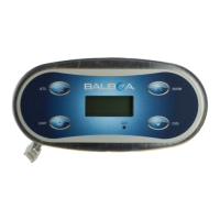
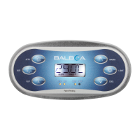
Panel Button Positions Aux Panel Information
Panel Button Assignments
1=Time
2=Mode/Prog
3=Temp Up
4=Temp Down
5=Light
6=Pump 1
7=Pump 2
8=J17/26 (when A7 is ON)
Supports 2-button aux panel
VX20
Supports 4-button aux panel
VX40D
6
67 85
7
1
2
3
4
8
6
5
7
Table 1 # of Hi-Speed
Pumps/Blower
Before Heat Disabled
A2 A10
OFF OFF 0
ON OFF 1
OFF ON 2
ON ON 3
Jumper Key
J12 Factory set. DO NOT MOVE.
Jumper must be on Pins 1 and 2 for VS51xZ/VS5xxSZ/VS5xxDZ software.
Jumper must be on Pins 2 and 3 for VS50xZ software.
J43 When jumper is placed on 2 pins during power-up, system will reset persistent memory.
Leave on 1 pin only to enable persistent memory feature.
 Loading...