Max. frequency response
BAE SA-OH-035: 500Hz
BAE SA-OH-036: 3kHz
Functional principle pulsed
Power supply indicator LED green (PWR)
Function indicator LED yellow (OUT)
Alarm indicator LED green (PWR) blinking
Alarm output 200mA, 50ms pulse length
Operating voltage 10 ... 30VDC (max.)
Output current 200mA
Current consumption (Ø / peak)
BAE SA-OH-035: 45mA/180mA
BAE SA-OH-036: 45mA/90mA
Weight 65g
Casing material ABS
Operating temperature -10°C bis +55°C
Protection class IP54
Wiring
VDC
brown
alarm
white
output
black
teach-in
pink/grey
GND
Z
L
Z
L
blue
NPN
VDC
brown
teach-in
pink/grey
alarm
white
output
black
GND
Z
L
Z
L
blue
PNP
V10 menu navigation
RUN
slide-switch JOG-Switch JOG-Switch JOG-Switch
selection of selection with +/- selection with +/- selection with +/-
main menu confi rm with confi rm with confi rm with
The actual setting is permanently lit up.
Flashing display means: indicated value can be selected. Confi rm by pushing JOG-switch.
Operation
The different operation modes and parameters are
set by a 4-position slide-switch and a JOG-switch with
push-button functionality.
Dismount
Mount
Put device onto DIN rail clip as shown.
Then, connect sensor cable.
First unplug sensor cable connector.
Then take amplifi er off the DIN rail clip as shown.
5
3
Connection
In- /Output
Sensor
1 (brown) + VDC
2 (white) remote teach
3 (blue) - GND
4 (black) signal output
3
1
4
M8 connector, 3pole
1 + emitter
4 GND/shielding
3 + receiver
1 (brown) + VDC
2 (white) alarm output
3 (blue) - GND
4 (black) signal output
5 (grey) remote teach
M12 connector, 5pole
1 (brown) + VDC
2 (white) alarm output
3 (blue) - GND
4 (black) signal output
brown + VDC
white alarm output
blue - GND
black signal output
pink remote teach
2m PVC-cable 5x0,14
M8 connector, 4pole
SA3: M8 connector, 4pole
4
1
3
2
1
2
4
slide-switch
JOG-switch
Output-
Mode
Option
0...250
0...250
dark-on
light-on
Parameter
lock
Turn dis-
play
Default
factory setting
Y E S
n o
Teach
fully automatic teach
1-point teach
2-point teach
Fine
tuning
Potentiometer
Threshold low
Threshold high
Alarm level
Operati-
+ RemoteTeach
0....999
Actual threshold high
Actual threshold low
(see teach-menu)
1...127
0...999
0...999
0...999
0...999
0...999
Signal
strength
+
-
Dark-On/
Light-On
ms
ms
level 0 level 1 level 2 level 3
TEA
OPT
OUT
Y E S
n o
Push
Off Delay
On Delay
- light-on/dark-on select;
- pulse stretching
- signal strength display;
- selected parameters:
( + = tHi , - = tLo )
- external TEACH
inscription function
JOG-switch
push-button
(confi rmation of selection)
increment
decrement
slide-switch
OUT
OPT
TEA
RUN
- operation modes
- teach-modes
+
-
Remote teach procedure
The switching threshold of the amplifi er can be
adjusted remotely through the PLC via the
teach-input (pink/grey).
(N.B.: only in RUN mode!).
The remote teach procedure is
actuated by two pulses from the
PLC to the amplifi er. The duration
of the fi rst pulse selects the teach
mode (automatic or 2-point).
The duration of the second pulse
defi nes the storage of the deter-
mined threshold value.
1.) X = 2,0 - 4,5s: Permanent storage (100.000 times max.); The successfull teach procedure is confi r-
med by a signal of 100ms duration on the alarm output.
2.) X = 0,1 - 1,5s: Non permanent storage (until next power cutoff); The successful teach
procedure is confi rmed by a signal of 100ms duration on the alarm output.
Required voltages PNP NPN
Input voltage Signal „1“: >9V <3V
Input voltage Signal „0“: <5V >6V
Input current: <3mA <3mA
b) Remote 2-point teach:
a) Fully automatic remote teach:
2,0 - 4,5 s
alarm pulse
1
0
signal from PLC
0,1 - 30 s
( teach duration)
X
(running process; preferably
several switching cycles)
teach point (condition1)
signal from PLC
X
0,1 - 30 s
0,1 - 1,5 s
alarm pulse
0
1
teach point (condition2)
0,1 s
Hysteresis
Hysteresis in %
4 values (default 12)
3; 6; 9; 12
Especially recommended for cyclic
processes.
Higher signal level should be teached rst.
hyst.
AbS
hyst.
hyst.
hyst.
hyst.
hyst.
hyst.
2 x hyst.
hyst.
hyst.
hyst.
hyst.
hyst.
nom. threshh.
nom. threshh.
nom. threshh.
Pt1
Pt2
tHi
ALH
tLo
ALH
ALH
ALH
tHi
tHi
tHi
tLo
tLo
tLo
signal
signal
tHi
tLo
ALH
alarm
output
Pushing the JOG-switch activates the teach procedure. Display rdy confi rms successful exe-
cution of the teach procedure.
- Repeat teach procedure after every change in hysteresis setting.
- Hysteresis recommendation: For distances > 50% of nominal => use values 9 or 12.
Push JOG-switch to start teach
procedure. Switching threshold
is adjusted by repeated inserting
and removing of the object in the
sensing beam.
Pushing of the JOG-switch
terminates the procedure.
The object is placed statically in
the sensing beam.
Single push on the JOG-switch
executes the teach procedure.
Positioning of object 1 (resp.
distance 1) in the sensing beam
=> Push JOG-switch;
Positioning of object 2 (resp.
distance 2) in the sensing beam
=> Push JOG-switch
Manual fi ne tuning of all relevant
parameters:
- for optimisation after automatic
teach or
- as fully manual adjustment
without automatic teach.
(Only recommended for pro-
cesses which cannot be adjusted
by one of the automatic pro-
cedures or for correction of an
automatic teach )
All automatic teach procedures:
min. value of calculated threshold = 100
max. value of calculated threshold = 850
Manipulation Action
Notice
teach menu and teach instruction
Back to level 1
If the green LED is blinking (alarm indicator)
when the amplifi er is in operation (RUN), it
indicates an unstable signal. In this case, check
whether the sensor is dirty or out of alignment.
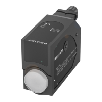
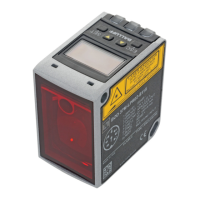
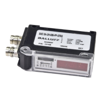
Photoelectric sensors
MICROmote® amplifi er BAE
Switching amplifi er for sensor heads BOH
Nr. 916402 Ausgabe / Edition Premium DE / EN / G14
Änderungen vorbehalten / subject to modifi cation
Caution! Sensor and amplifi er are only intended for object detection. Do not use amplifi er and
sensor for personnel safety applications!
Technical data
Ordercode Switching amplifi ers Premium
www.balluff.com
rEt: return to level 1
The nominal switching
threshold is calculated as
mean value of the detected
high und low signal level.
ALH, tHi und tLo are deter-
mined referring to it depen-
dent on selected hysteresis.
Nominal switching threshold,
ALH, tHi, and tLo are adjusted
automatically refer-ring to the
signal level in a (fi xed) relation
to each other.
The nominal switching
threshold is calculated as
mean value between Pt1 and
Pt2.
ALH, tHi und tLo are deter-
mined referring to it depen-
dent on hysteresis.
POt: Adjustment of signal
amplifi cation in 127
potentiometer steps.
AbS:The nominal switching
threshold may be moved
manually.
tLo, tHi, ALH remain
in the before auto-
matically adjusted
relation to each other.
tLo: threshold low
tHi: threshold high
ALH:alarm level
BAE00R0 BAE SA-OH-035-PP-S92G
BAE SA-OH-035-NP-S92G
BAE00NF BAE SA-OH-035-PP-S75G
BAE00PT BAE SA-OH-035-NP-S75G
BAE00PZ BAE SA-OH-035-PP-S75G-SA3
BAE SA-OH-035-NP-S75G-SA3
BAE00R2 BAE SA-OH-036-PP-DV02
BAE SA-OH-036-NP-DV02
BAE SA-OH-036-PP-S92G
BAE SA-OH-036-NP-S92G
BAE00R3 BAE SA-OH-036-PP-S75G
BAE SA-OH-036-NP-S75G
BAE SA-OH-036-PP-S75G-SA3
BAE SA-OH-036-NP-S75G-SA3
 Loading...