63
63
english
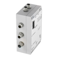
Wiring diagram
for BIS C-6002
processors with
adapter BIS C-650
Terminal location and
designation
Terminal
block
PROFIBUS-DP
Supply voltage,
input/output
Protection
ground PE
BIS C-6002-...-KL2
Interface Information / Wiring Diagrams
The ground connector should be connected to
earth directly or through a RC combination de-
pending on the system (potential counterpoise).
When connecting the bus leads, make sure that the
shield has proper connection to the PG housing.
Please note the assembling instructions on
60.
7654321
DGND A B VP DGND A B
PROFIBUS-DP
13 12 11 10 9 8
+IN –IN +V
SO
–V
SO
01 02
INPUT OUTPUT
19 18 17 16 15 14
+VS –VS TxD RxD GND
POWER RS 232
Terminal block connections
01 = CT Present 1
02 = CT Present 2
C60_2-019_818217_0806-e.p65
64
english64
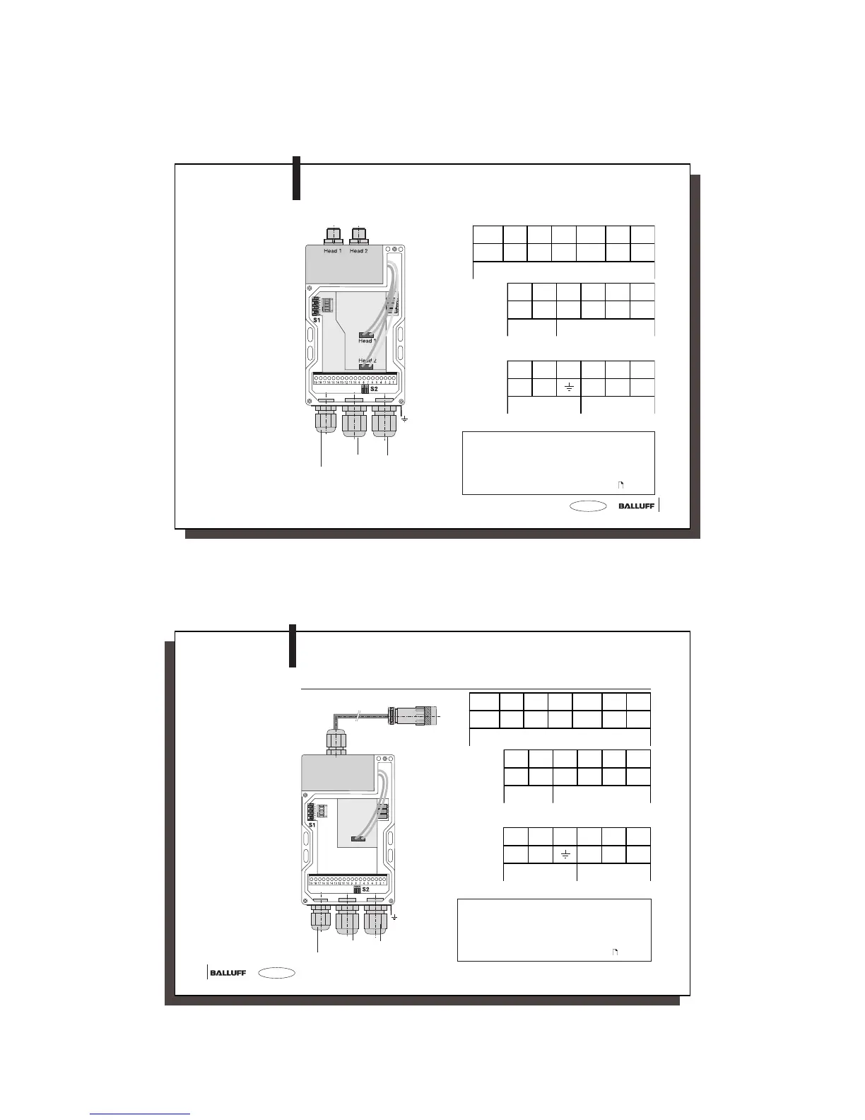
Terminal block connections
The ground connector should be connected to
earth directly or through a RC combination de-
pending on the system (potential counterpoise).
When connecting the bus leads, make sure that the
shield has proper connection to the PG housing.
Please note the assembling instructions on
60.
Terminal for read/write head (8 pin)
Terminal location and
designation
Terminal
block
PROFIBUS-DP
Supply voltage, input/output
Protection
ground PE
BIS C-6002-...-KL2
Interface Information / Wiring Diagrams
Wiring diagram
for BIS C-6002
processors with
adapter BIS C-670
7654321
DGND A B VP DGND A B
PROFIBUS-DP
13 12 11 10 9 8
+IN –IN +V
SO
–V
SO
01 02
INPUT OUTPUT
19 18 17 16 15 14
+VS –VS TxD RxD GND
POWER RS 232
01 = CT Present 1
02 = CT Present 2