65
65
english
Remote bus cable
for PROFIBUS-DP
To insert BIS C-6002-...-ST11 processor into the serial PROFIBUS-DP, there are the terminal
X2 for the PROFIBUS input and the terminal X3 for the PROFIBUS output.
...
1
2
3
4
1
2
3
4
A
B
VP
DGND
A
B
VP
DGND
A
B
A
B
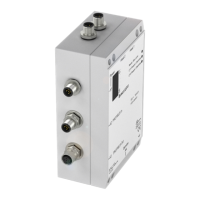
In case the processor is the last bus module in the chain, then only the incoming cable is con-
nected to X2.
The last bus module must terminate the bus with a resistor. In the case of the BIS C-602, this
can be realized in two different ways:
1. In the device by closing the switch S2
(factory standard is open)
Note: Output terminal must be closed
off with a screw cover in order to
maintain the enclosure rating.
2. Outside the device in a connector to socket X3. In this case the signal VP (pin 1) and
DGND (pin 3) should be brought out in order to connect the external resistor to the poten-
tial. Note: In this case S2 has to be open!
BIS C-6002-...-ST11
Interface Information / Wiring Diagrams
Bus station BIS C-6002-...-ST11
Bus station Bus station
5-pin female
X3, output
5-pin male
X2, input
Output Input
Connect shield
to connector
housing
Connect shield
to connector
housing
S2 Terminating resistor
closed active
open passive
green
red red
green
C60_2-019_818217_0806-e.p65
66
english66
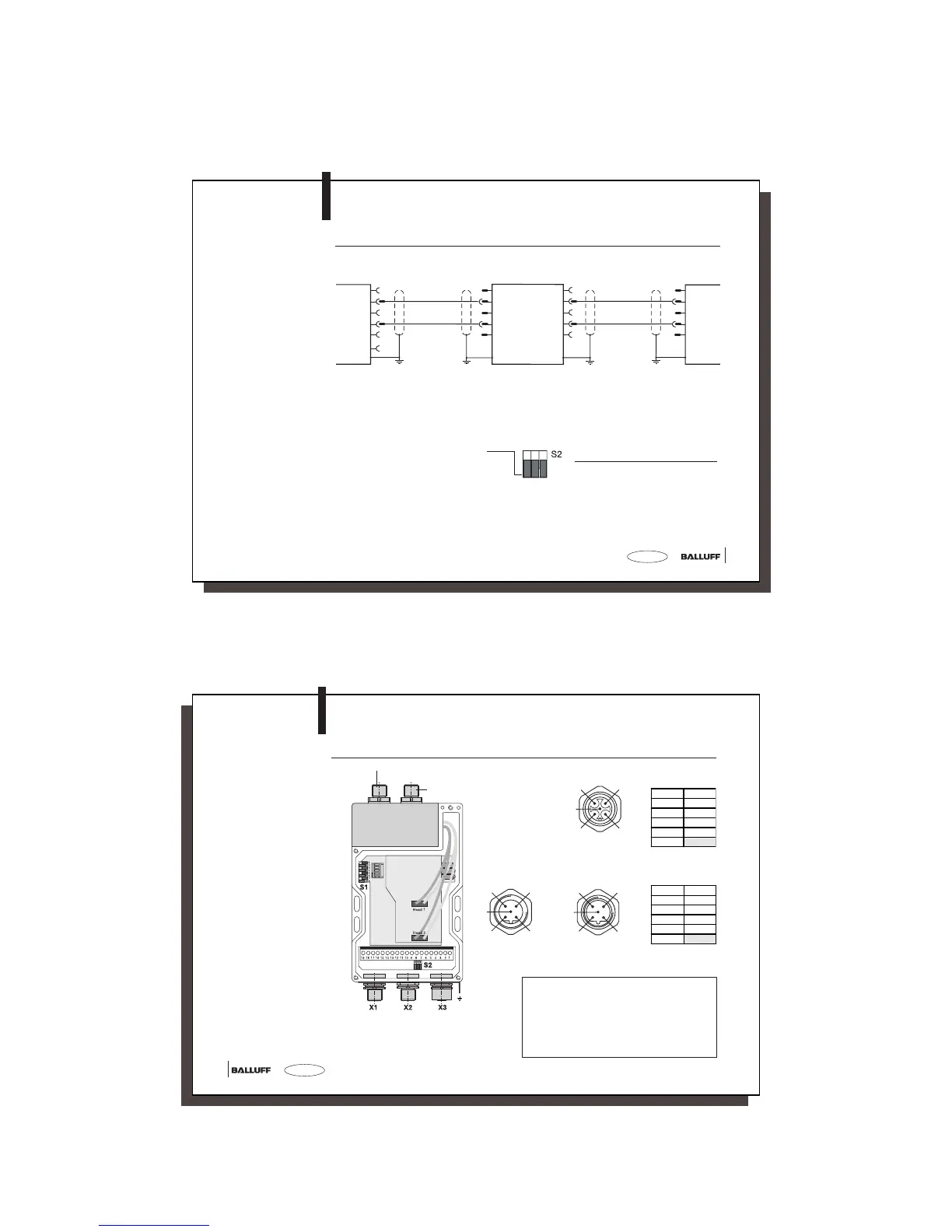
Wiring diagram for
BIS C-6002-...-ST11
processor with
adapter BIS C-650
PROFIBUS-DP
Supply
voltage,
digital input
Protection
ground PE
BIS C-6002-...-ST11
Interface Information / Wiring Diagrams
1
2
3
5
4
X1, supply voltage, digital input
X2, PROFIBUS-
input (male)
1
2
3
5
4
n.c. = do not connect
X3, PROFIBUS-
output (female)
2
1
4
5
3
Pin Function
1VP
2A
3DGND
4B
5
n.c.
Pin Function
1+Vs
2–IN
3–Vs
4+IN
5
n.c.
Connection for Read/Write Head 1
The ground connector should be connected to
earth directly or through a RC combination
depending on the system (potential counter-
poise).
When connecting the bus leads, make sure
that the shield has proper connection to con-
nector housing.
Terminal location
and designation
Connection for
Read/Write Head 1