67
67
english
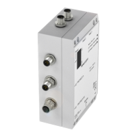
Wiring diagram for
BIS C-6002-...-ST11
processor with
adapter BIS C-654
PROFIBUS-DP
Supply volt-
age, digital
input
Terminal location
and designation
Protection
ground PE
The ground connector should be connected to earth directly or through a RC combination depending on the system
(potential counterpoise).
When connecting the bus leads, make sure that the shield has proper connection to connector housing.
BIS C-6002-...-ST11
Interface Information / Wiring Diagrams
1
2
3
5
4
X1, supply voltage, digital input
X2, PROFIBUS-
input (male)
1
2
3
5
4
X3, PROFIBUS-
output (female)
2
1
4
5
3
Pin Function
1VP
2A
3DGND
4B
5
n.c.
Pin Function
1+Vs
2–IN
3–Vs
4+IN
5
n.c.
Connection for
Read/Write Head
BIS C-355/...S92
The BIS C-6002-654-03-ST11 processor may only be
operated in a compatible mode. This means switch S1/8
must be in the CN position (see
13). Please refer to the
manual for BIS C-6_2 for the parameter values and enabling
the "Select both heads" function and use the GSD file
C6x2.
.
n.c. = do not connect
C60_2-019_818217_0806-e.p65
68
english68
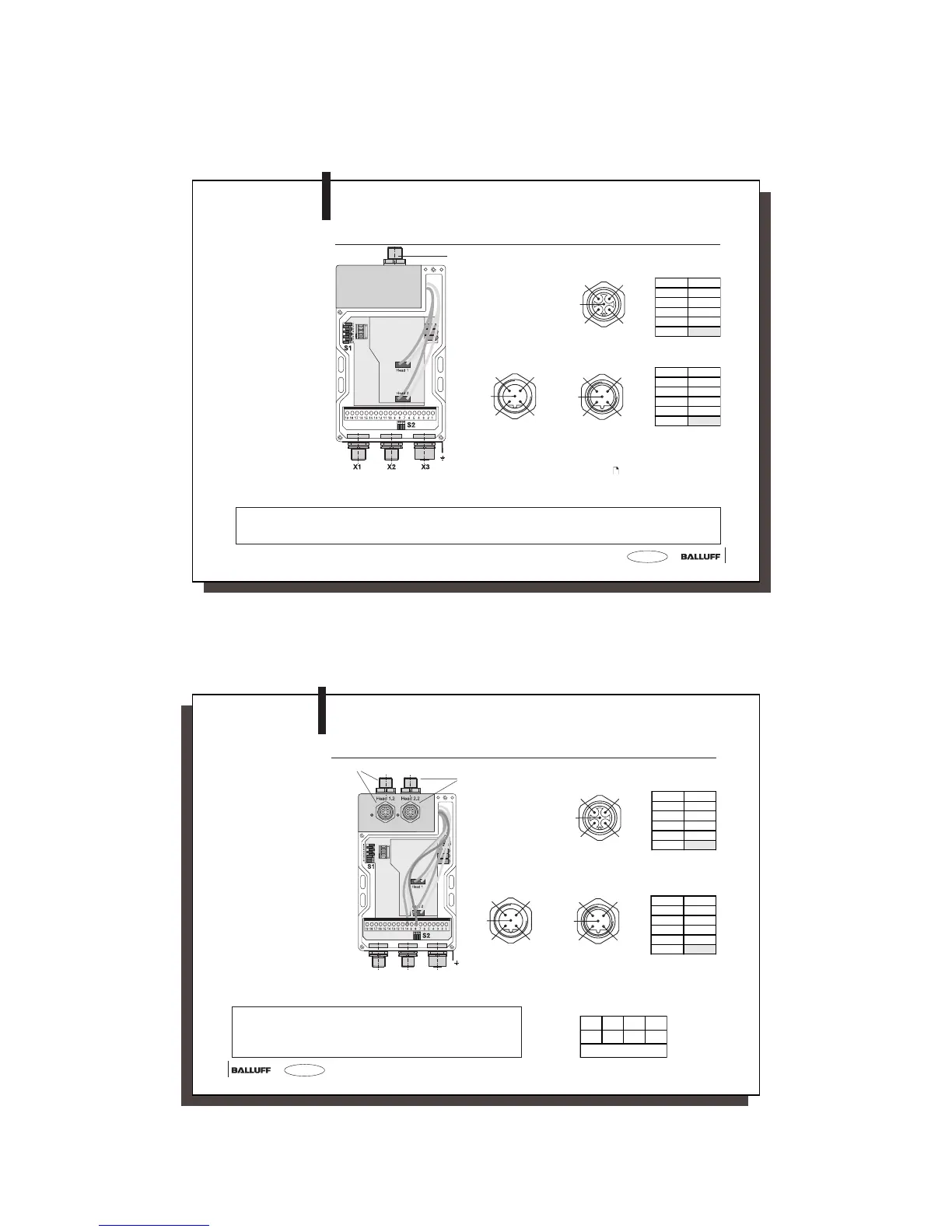
Wiring diagram
for BIS C-6002
processors with
adapter BIS C-655
(2 × 2 heads)
BIS C-6002-019-655-03-ST11
Interface Information / Wiring Diagrams
The ground connector should be connected to earth directly or through
a RC combination depending on the system (potential counterpoise).
When connecting the bus leads, make sure that the shield has proper
connection to connector housing.
Connection for Read/Write Heads 1.1/1.2
Connection for
Read/Write Heads
2.1/2.2
Supply voltage,
digital input
PROFIBUS-DP
Function ground
FE
1
2
3
5
4
X1, supply voltage, digital input
X2, PROFIBUS-
input (male)
1
2
3
5
4
n.c. = do not connect
X3, PROFIBUS-
output (female)
2
1
4
5
3
Pin Function
1VP
2A
3DGND
4B
5
n.c.
Pin Function
1+Vs
2–IN
3–Vs
4+IN
5
n.c.
☞
11 10 9 8
BK YE GY
Head Select
Terminal block connections