75
75
english
Mounting the
BIS C-6022
processor
BIS C-6022
Mounting Processor
The processor is mounted using 4 M4 screws.
M4
ca. 15
63
100
60
ca. 20
ca. 15
145
160
Head 2 Head 1
X1
X4
X2
X3
C60_2-019_818217_0806-e.p65
76
english76
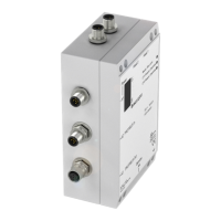
Head 2 Head 1
X1
X2
X3
X4
Connection for read/write head 2 Connection for read/write head 1
BIS C-6022
interfaces
Connection locations
and names
Protection ground PE
To set the PROFIBUS-DP address, activate or deactivate the internal termination resistor, set
the compatibility mode or to change the EEPROM, you must open up the BIS C-6022 proces-
sor.
Remove the 4 screws on the BIS C-6022 and lift off the cover. See the following
for addi-
tional information.
Opening the
BIS C-6022
processor
BIS C-6022
Opening the processor / Interface information
PROFIBUS-DP
PROFIBUS-DP
Supply voltage,
input,
output (ST10 only)
Be sure before
opening that the unit
is disconnected
from power.
Mounting of the cover
(4 screws),
max. permissible tightening
torque: 0.15 Nm
Service interface