79
79
english
Head 2 Head 1
X1
X2
X3
1
2
3
4
5
6
7
8
Head 1
Head 2
19181716151413121110987654321
S1
S2
X4
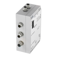
BIS C-6022-...-ST10
Interface Information / Wiring Diagrams
Wiring diagram for
BIS C-6022-...-ST10
processor
X1, supply voltage, digital input, and
CT Present outputs
X2, PROFIBUS output
X3, PROFIBUS input
n.c. =
do not connect!
The ground connector should be connected to earth directly or through
a RC combination depending on the system (potential counterpoise).
When connecting the bus leads, make sure that the shield has proper
connection to connector housing.
Pin Function
1+Vs
2 CT Present 2
3–Vs
4+IN
5 CT Present 1
Pin Function
1DGND
2A
3
n.c.
4B
5
n.c.
6VP
7 +24 V
8GND
9
10 ... 12
n.c.
☞
1
2
3
4
X4, Service interface
Pin Function
1
n.c.
2TxD
3GND
4RxD
Protection
ground PE
C60_2-019_818217_0806-e.p65
80
english80
Head 2 Head 1
X1
X2
X3
1
2
3
4
5
6
7
8
Head 1
Head 2
19181716151413121110987654321
S1
S2
X4
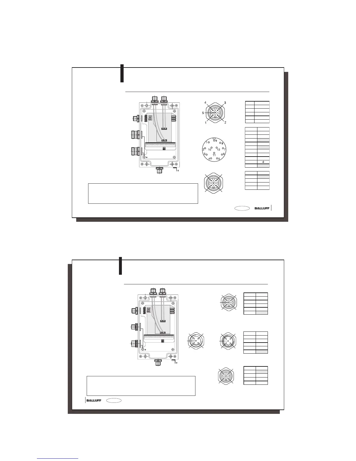
BIS C-6022-...-ST14
Interface Information / Wiring Diagrams
Wiring diagram for
BIS C-6022-...-ST14
processor
X1, supply voltage, digital input
n.c. =
do not connect!
The ground connector should be connected to earth directly or through
a RC combination depending on the system (potential counterpoise).
When connecting the bus leads, make sure that the shield has proper
connection to connector housing.
1
2
3
5
4
X2, PROFIBUS
input (male)
1
2
3
5
4
X3, PROFIBUS
output (female)
2
1
4
5
3
Pin Function
1VP
2A
3DGND
4B
5
n.c.
Pin Function
1+Vs
2–IN
3–Vs
4+IN
5
n.c.
Protection
ground PE
☞
1
2
3
4
X4, Service interface
Pin Function
1
n.c.
2TxD
3GND
4RxD