81
81
english
Changing the
EEPROM in the
BIS C-6022
processor
BIS C-6022
Changing the EEPROM
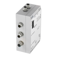
To change the EEPROM, open the processor as described on 76.
Be sure before opening that the unit is
disconnected from power.
To avoid damaging the EEPROM, please
observe the requirements for handling
electrostatically sensitive components.
The EEPROM is replaced by unplugging
and plugging back into the socket.
Head 2 Head 1
X1
X2
X3
1
2
3
4
5
6
7
8
Head 1
Head 2
19181716151413121110987654321
S1
S2
X4
Location of the
EEPROM
C60_2-019_818217_0806-e.p65
82
english82
Dimensions, weight Housing Metal
Dimensions 190 x 120 x 60 mm
Weight 820 g
Ambient temperature 0 °C to +60 °C
Protection class IP 65 (when connected)
Integral connector X1 for V
S
, CT Present_, +IN 5-pin (male)
Round connector X2 / X3 for PROFIBUS-DP 12-pin (female)
Integral connector X4 for Service interface 4-pin (male)
Integral connector X1 for V
S
, +IN 5-pin (male)
Integral connector X2 for PROFIBUS-DP input 5-pin (male)
Integral connector X3 for PROFIBUS-DP output 5-pin (female)
Integral connector X4 for Service interface 4-pin (male)
Supply voltage V
S
DC 24 V ± 20 %
Ripple ≤ 10 %
Current draw ≤ 400 mA
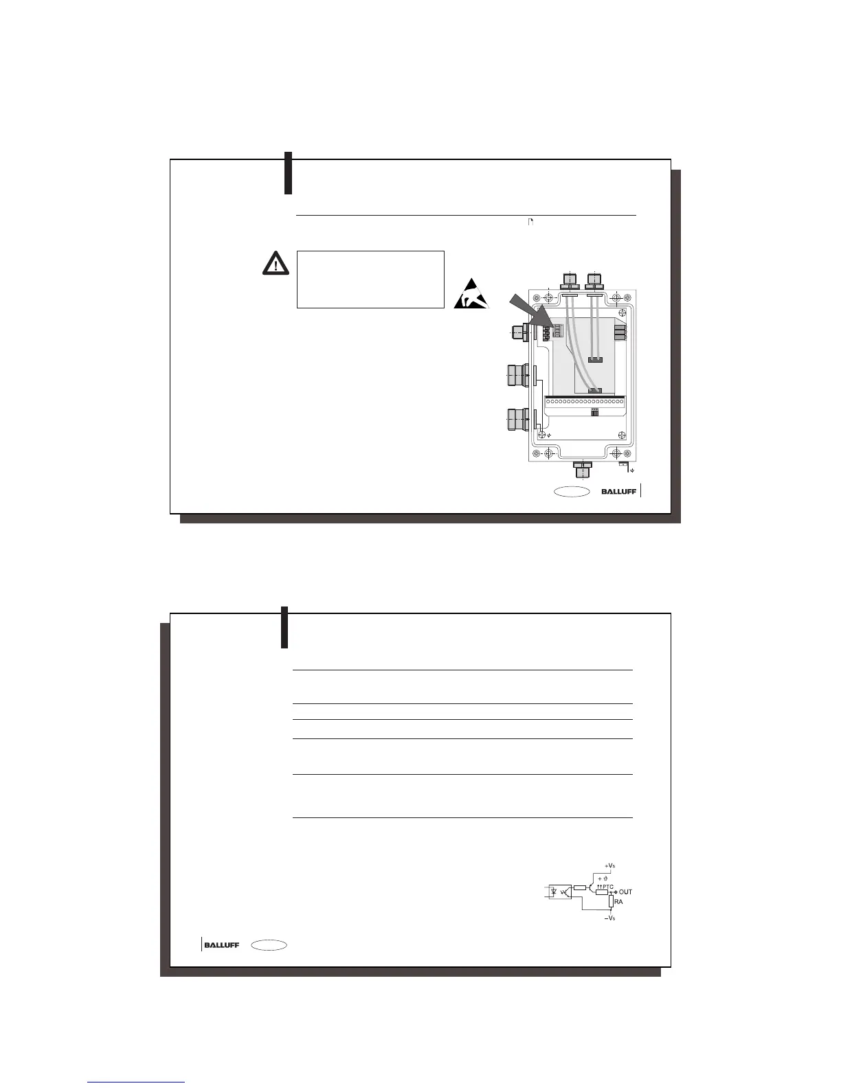
Control outputs CT Present 1 and 2 Optocoupler isolated
Output circuit PNP (current sourcing)
Operating voltage V
S
for output DC 24 V ± 20 % via X1
Ripple ≤ 10 %
Output current max. 20 mA
Voltage drop at 20 mA approx. 2.5 V
Output resistance R
A
10 kΩ to –V
S
BIS C-6022
Technical Data
Operating conditions
Connections
BIS C-6022-...-ST14
Enclosure
Electrical
connections
Connections
BIS C-6022-...-ST10
with ST10 only: