2
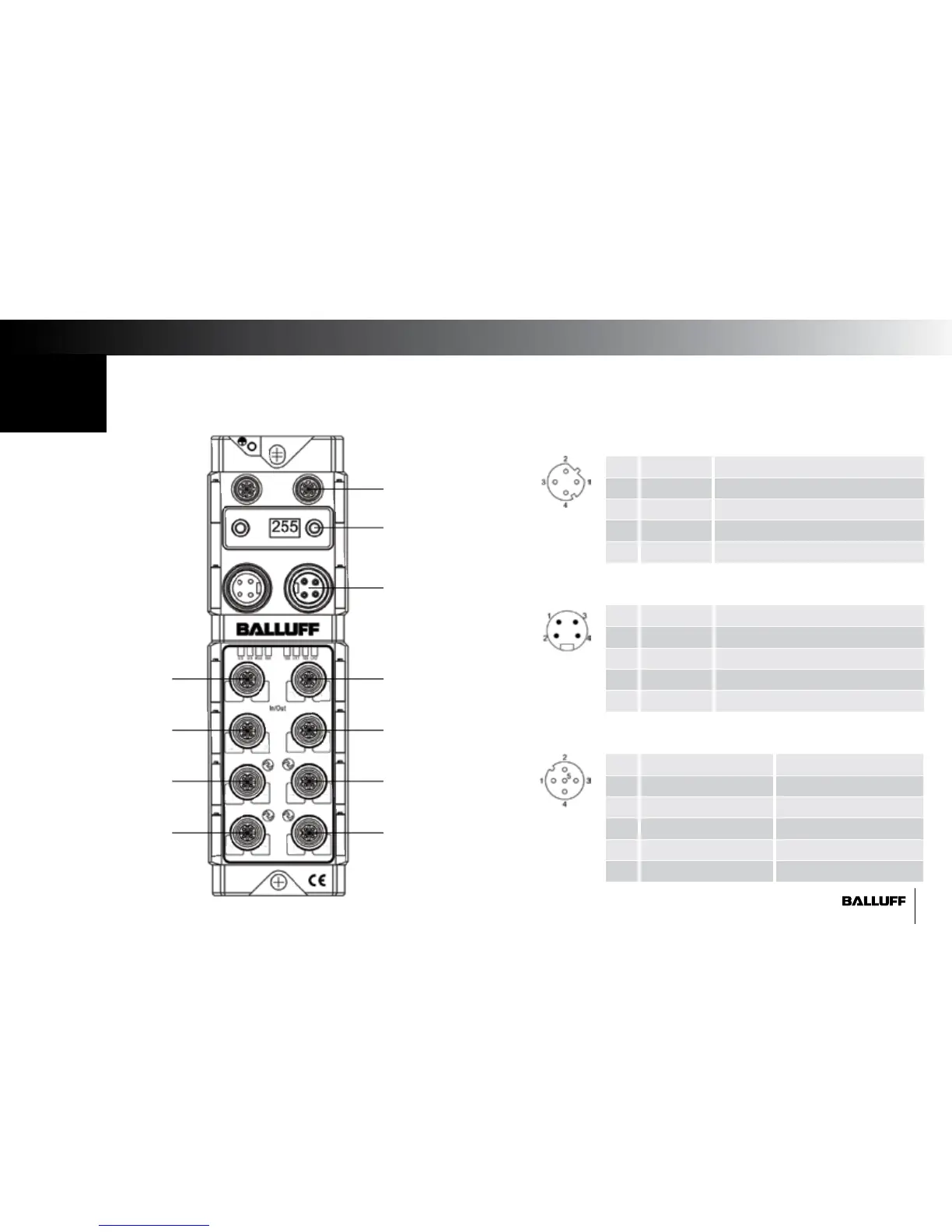
Connect the Distributed Modular I/O Master Block
1
1. Using an M12 D-coded EtherNet/IP cable, connect the block to the Ethernet network.
2. Power up the block using 24VDC and a 7/8" 4pole connector wired according to the below diagram.
3. Set the IP address of the block using the pushbutton display. For instructions on operating the display, see the manual.
Port 0
Port 1
Port 2
Port 3
Port 4
Port 5
Port 6
Port 7
IO-Link 1
IO-Link 2
IO-Link 3
IO-Link 4
Pin Function Description
1 TX + Transmit Data +
2 RX + Receive Data +
3 TX - Transmit Data -
4 RX - Receive Data -
M12 Network Port
Pin Function Description
1 + 24 V Actuator Supply
2 + 24 V Sensor/Bus Communication Supply
3 0 V Sensor/Bus Communication Supply
4 0 V Actuator Supply
7/8" Auxiliary Power Port
Pin Configurable Port IO-Link Port
1 + 24 V + 24 V
2 Input 2 or Output 2 Input/Output 2
3 0 V 0 V
4 Input 1 or Output 1 IO-Link or Input/Output 1
5 FE FE
M12 I/O Port
Network
Aux Power
Pushbutton Display
IP address subnet mask
gateway
00 01
04
1514
13
12
1110
09
06 07
08
05
0302