Do you have a question about the Balluff BNI IOL-719-002-Z012 and is the answer not in the manual?
| Interface | IO-Link |
|---|---|
| IO-Link Port Class | Class A |
| Number of Ports | 8 |
| Number of IO-Link Ports/Channels | 4 |
| Operating voltage Ub | 24 V DC |
| Rated operating voltage Ue DC | 24 V |
| Voltage Supply | 24 V DC |
| Protection Class | IP67 |
| Housing Material | Plastic |
| Storage Temperature | -40 to +85 °C |
| Connection | M12 |
Explains the organizational structure of the user guide.
Details the formatting conventions used throughout the guide.
Defines the meaning of symbols used in the manual for clarity.
Lists and defines common abbreviations used in the documentation.
Notes that product images may differ from actual products.
Specifies the intended application and purpose of the Balluff Network Interface.
Provides critical information and warnings for product installation and initial operation.
Covers essential safety guidelines, authorized personnel, and operating company obligations.
Details the resistance of BNI modules to chemicals and oils.
Warning regarding electrical hazards and necessary precautions.
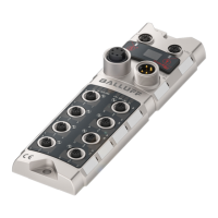
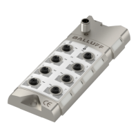
Illustrates and labels the physical connection points of the device.
Describes how to physically mount and attach the BNI IOL-719-002-Z012 module.
Details the electrical wiring and connection procedures for the device.
Explains the IO-Link M12 connector pinout and function.
Instructions on connecting the IO-Link line to the sensor hub.
Guidance on proper grounding connection for optimal performance.
Lists available module versions and their corresponding analog functions.
Describes the configurable analog port capabilities and supported input types.
Details the pin assignments for various sensor types on the I/O ports.
Specifies the supported input signal ranges for different analog modes.
Explains how digitalized analog values are represented in process data.
Details the calculation formulas for signed data representation of analog values.
Explains calculations for unsigned data format and its resolution.
Describes how analog values are converted and sent in dimensioned format.
Provides technical data and specifications for the IO-Link communication.
Details the bit allocation for analog input values and switch points in process data.
Describes error bits like short circuit, underflow, and overflow in output data.
Lists and explains various configurable parameters and their settings.
Configuration of the device's serial number for master validation.
Defines data justification (left/right) for analog values in process data.
Sets the operating mode for each analog input port.
Configures the bit resolution for analog input values.
Allows selection of input pins (2 or 4) for voltage or current inputs.
Selects the measurement method for Pt sensors (2, 3, or 4 wire).
Enables or disables wire break detection for certain sensor types.
Specifies the format (signed, unsigned, dimensioned) of process data.
Configures the first threshold for detecting analog value changes.
Configures the second threshold for detecting analog value changes.
Enables or disables the switch point functionality for each port.
Sets the grounding mode for thermocouples to ensure accurate measurement.
Lists and describes error codes for device malfunctions.
Details event codes related to IO-Link revision and device status.
Provides the physical dimensions and mounting details of the device.
Details the housing material and port specifications.
Specifies operating conditions, current draw, and measurement errors.
Defines the environmental and operational parameters for the device.
Explains the meaning and function of the device's status LEDs.
Details how the product ordering code is structured and its components.
Provides ordering codes and lists the included material with the product.