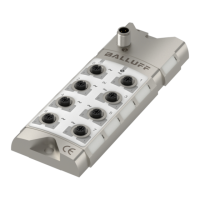
Balluff Network Interface / IO-Link BNI IOL-719-002-Z012
www.balluff.com
Switch point
1, F6hex
Switch point
2, F7hex
Two switch points can be set for each port. When the analog value is greater than the value of
the switch point, the corresponding bit in the process data will be set.
Each switch point ISDU register is 16 byte long. Accessing the ISDU register through the
subindex 0, the switch point values for all ports can be read/written. Accessing the ISDU register
through subindex 1 – 8, the switch point for the corresponding port (P0 – P7) can be read/written.
In order to avoid flickering of the switch point bit in process data, the switchpoint is evaluated with
hysteresis. The hysteresis for different input types are listed in the table above.
Note
The switch point value must be set according to the resolution and process data format.
The switch point value is always right justified.
Switch point
enable F8hex
Each switching point can be enabled or disabled. When a switch point is disabled, the
corresponding bit in the process data will be set to 0. When a switch point is enabled, the analog
value will be compared to the switch point value, and the corresponding bit will be set in the
process data according to the result of the comparison.

 Loading...