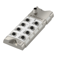
Balluff Network Interface / IO-Link BNI IOL-719-002-Z012
www.balluff.com
The BNI IOL-719-002-Z012 supports many standard input signal ranges. In some cases an
analog sensor has higher linear output range than the nominal output range. For example a
sensor with a 0 – 10 V output can source voltages between -0.5V and 10.5V, and indicates
error with a signal <-0.5V or >10.5V. Therefore the BNI IOL-719-002-Z012 has the following
input ranges for the different analog modes.
The signal on the input port of the BNI IOL-719-002-Z012 will be digitalized and sent as a
process data over IO-Link. There are 16 bits reserved in the process data for each port. The
digitalized value can be represented in different formats (signed, unsigned or dimensioned),
in different resolution (16, 14, 12 or 10 bit), with different alignment (left or right aligned).

 Loading...