Balluff Network Interface / IO-Link BNI IOL-719-002-Z012
www.balluff.com
3.2. Mechanical
connection
The BNI IOL-719-002-Z012 modules are attached by using 2 M6 screws and 2 spacers.
3.3. Electrical
connection
The BNI IOL-719-002-Z012 modules require no separate supply voltage connection. Power
is provided through the IO-Link interface by the host IO-Link Master.
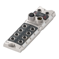
IO-Link (M12, A-coded, male)
Power supply controller, +24V, max 1.1A
C/Q, IO-Link data transmission channel
Connecting the
Sensor Hub
Connection protection ground to FE terminal, if present.
Connect the incoming IO-Link line to the Sensor Hub.
Note
A standard 3 wire sensor cable is used for connection to the host IO-Link master.
Note
The FE connection from the housing to the machine must be low-impedance
and kept as short as possible.
 Loading...