7
Reading the Process Data – Outputs
5b
It is important to note that every standard I/O on the block is setup as a freely configurable port. If the controller is programmed to look for an input
and there is an input wired there, it will be an input. If the controller is programmed to fire an output, it will be an output there. There are diagnostic
inputs available that will indicate an overload on an output from the master block.
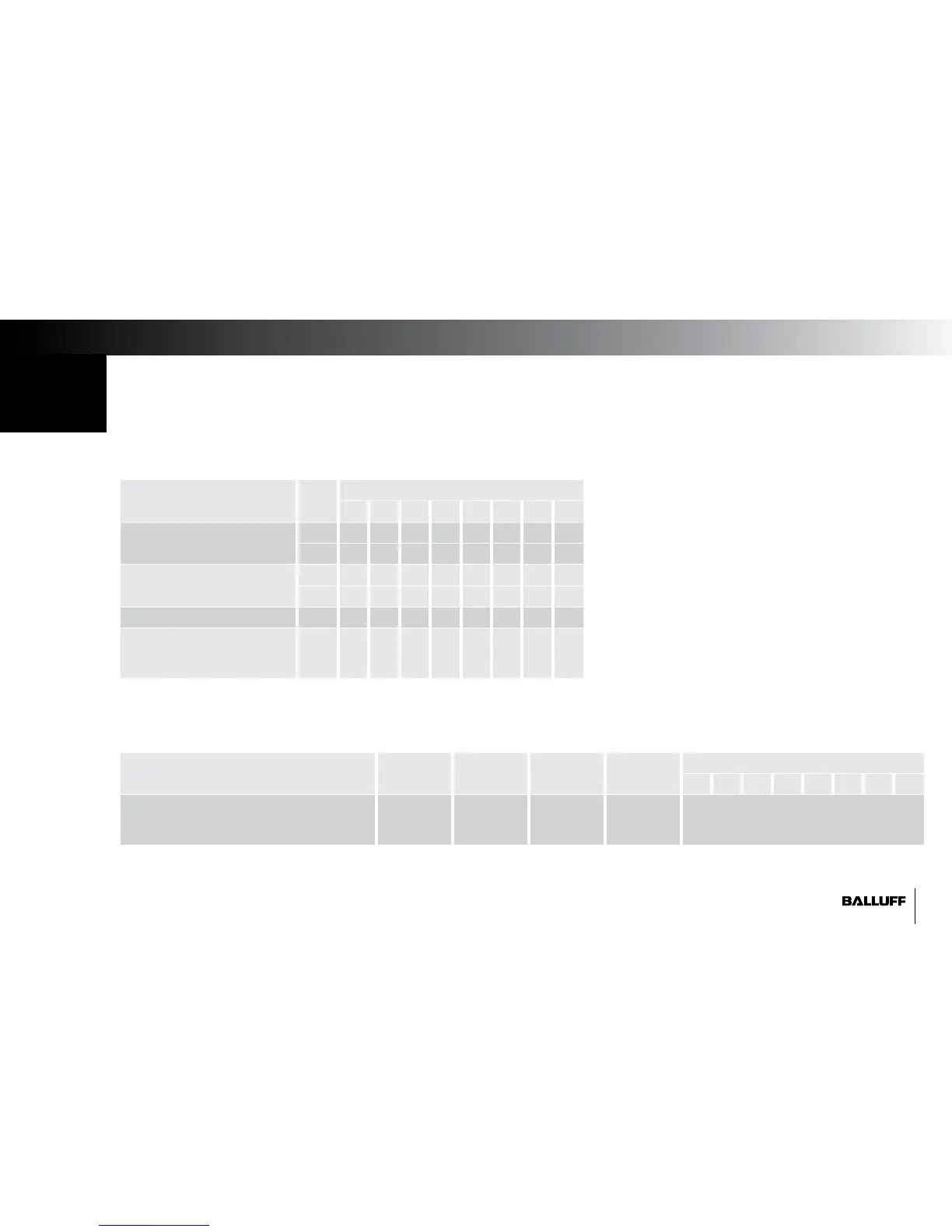
Description Byte Bit (block pin #)
7 6 5 4 3 2 1 0
Output Data
(Pin Number of Output)
0 07 06 05 04 03 02 01 00
1 15 14 13 12 11 10 09 08
Restart Output (after overload)
(Pin Number of Output)
2 07 06 05 04 03 02 01 00
3 15 14 13 12 11 10 09 08
Reserved Data 4 0 0 0 0 0 0 0 0
DL: Display Lock / PLC Lock
GN: Display Green LEDs ON
RD: Display Red LEDs ON
5 0 0 0 0 0 DL GN RD
Standard Output Data
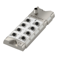
IO-Link Ports – Output Data
Description IO-Link 1 IO-Link 2 IO-Link 3 IO-Link 4 Bit
7 6 5 4 3 2 1 0
IO-Link Slave Device Specific Data 6...37 38...69 70...101 102...133 IO-Link Slave Device - 32 bytes of Output
(For bitmap details, see slave device
manual)
(organized by bytes of data in the input buffer of the master block)
(organized by bytes of data in the input buffer of the master block)