www.balluff.com 7english
4
Product description
4.3 Operating and display elements
4.3.1 Operating mode switch (receiver only)
Setting Meaning
L Light on / NO contact
D Dark on / NC contact
Tab. 4-1: Operating mode switch
4.3.2 Sensitivity setting (receiver only)
The rotary switch can be used to configure the sensitivity
and range of the receiver.
NOTICE
Product damage
If the sensitivity setting is turned past the end stop, the
setting function can be damaged.
► Do not turn the potentiometer past the mechanical
end stop at 270°.
Setting Meaning
Turn clockwise Increase sensitivity.
Turn
counterclockwise
Reduce sensitivity.
Tab. 4-2: Sensitivity setting
4.3.3 LED indicators
LED Meaning
Yellow
1)
Operating indicator: The LED lights
up as soon as the transmitter is
active.
Green
2)
Stability indicator: The LED lights
up as soon as the sensor is
operational and is operating in a
safe range.
1)
Transmitter only
2)
Receiver only
Tab. 4-3: LED
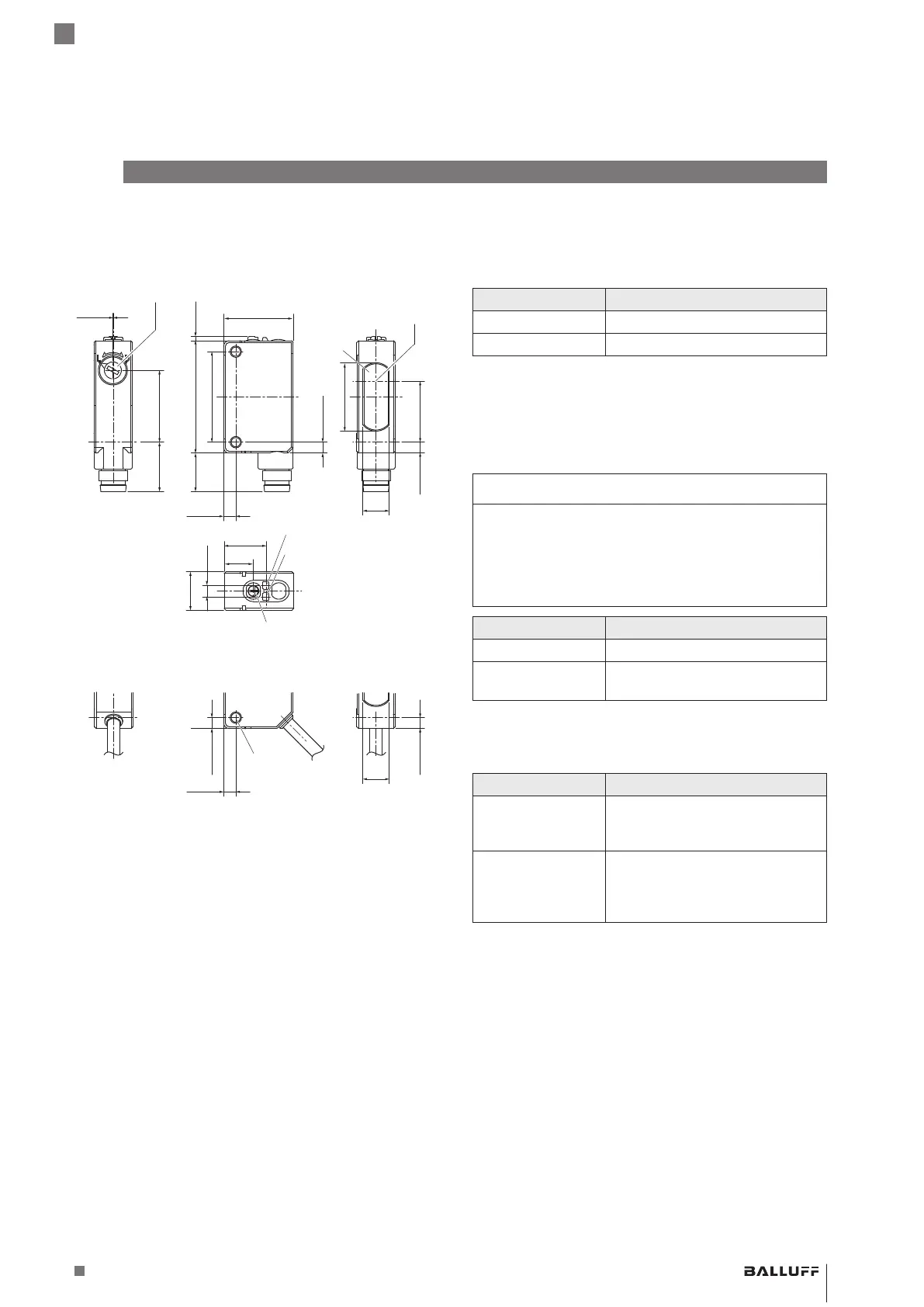
4.1 Construction
BOS R090K- _ U-RX10-S49
BOS R090K- _ U-RX10-S75
10.8
3.2
8.2
11.8
19.2
(3.1)
17.1
19.5
31.5 1.2
25.4
3.4
10.8
(3.1)
0.1
(13.9) 20.2
7.4
Opticalaxis
Lens
Yellow LED
1)
Green LED
2)
Setting the operating mode
Sensitivity setting
2)
BOS R090K- _ U-RX10-02
(3.1)
7.4
2-M3
3.4
10.8
3.2
8.2
11.8
19.2
(3.1)
17.1
19.5
31.5 1.2
25.4
3.4
10.8
(3.1)
0.1
(13.9) 20.2
(3.1)
1)
Transmitter only
2)
Receiver only
Fig. 4-1: Dimensions, design and function
4.2 Function
Through-beam sensors are sensors with separate
transmitter and receiver units, which must be
aligned to each other on both sides of the detection path.
When an object interrupts the light beam, the receiver
switches, i.e. the output signal changes.
BOS R090K-_U-RX10-S49/S75/02
Optoelectronic sensors – Through-beam sensors
 Loading...


