www.balluff.com 2
No. 942818-726 EN · 01.Vorserie · C19; Subject to modification. Replaces A19.
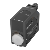
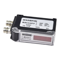
BSP B/M/V _ _ _ - _ _ _ _ _ - P00S2B - S4(- _ _ _ )
Pressure Sensors with IO-Link
english
Installation
DANGER
Risk of death
Risk of death from flying parts, escaping medium and
electrical shock.
► Always install pressure sensors with pressure and
power turned off!
► Operate the device only within specifications (as per
data sheet)!
NOTICE
Damage to the sensor
High temperatures and rapid pressure spikes beyond the
specified limits can result in damage to the sensor.
► Do not exceed limits (see Technical Data)!
NOTICE
Damage to the membrane
The membrane on the front flush sensor is very sensitive
to mechanical stresses.
► Do not touch the membrane!
► Wait until shortly before installation to remove
the packaging and cover cap, to ensure that the
membrane is not damaged. Retain the cover cap.
Installation notes
– If there is a risk of damage from lightning strike or
overvoltage, insert an overvoltage protection between
the feed device resp. control cabinet and the device.
– For hydraulic systems position the device so that the
pressure connection faces up (venting).
– When using in steam lines provide a cooling line.
– Installation must not cause any mechanical stress at
the pressure connection.
– Front flush sensors: Attach clamp fittings using a
suitable connecting element (e.g. half-ring or snap ring
connection) per manufacturer specifications.
When installing outdoors or in damp surroundings observe
the following:
– Make the electrical connection as soon as the device is
installed. Otherwise prevent moisture entry using an
appropriate cover cap or similar.
– Install the device so that it is protected from direct
sunlight.
– Devices with gauge reference in the housing must be
installed so that the gauge reference required for the
measurement is protected against dirt and moisture.
– In damp surroundings and when the device is wet, do
not turn the display to the desired position or operate
the buttons.
Installation
Check before installation:
– Is an appropriate seal available?
– Does the sealing surface have a flawless surface?
For pressure sensors with external threads do not use any
additional sealing material such as tow, hemp or Teflon
tape!
► Tighten the device by hand in the holding threads. Use
an appropriate open-end wrench to tighten and
observe the following tightening torques:
Tightening
torque
Connection
per DIN3852
Connection
per EN837
NPT
connection
1/4" approx.
5Nm
approx.
20Nm
approx.
30Nm
1/2" approx.
10Nm
approx.
50Nm
approx.
70Nm
Electrical Connection
The units come with selectable outputs which can be
configured either on the unit or via IO-Link.
Round connector M12x1
A-coded (4-pin)
Pin Signal
1 Supply +
2 (Out2)
PNP/NPN/4…20mA/0…10V (selectable)
3 Supply –
4 (Out 1)
PNP/NPN/IO-Link (selectable)
Display and operating elements
1 2 3 4
5
6
7
1 Four red LEDs for
units selection (bar,
mbar, PSI, MPa)
2 LED IO-Link (red):
Status indicator for
IO-Link
3 LED Out 1 (yellow):
Status indicator for
Switching Output 1
4 LED Out 2 (yellow): Status indicator for Switching Output 2
5 Red 7-segment display for measurement value and
parameters
6 Button for menu selection and confirming/entering
7 Button for moving within the menu

 Loading...