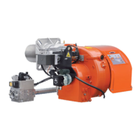
ASSEMBLING THE GAS TRAIN
The EN 676 approved gas train is sold separately from the burner.
There are different ways of assembling the valve train, as shown in
drawing 0002937060.
Choose the most rational position for the set-up of the boiler room and
the position in which the gas pipeline arrives.
DANGER / ATTENTION
In case of very large valves, e.g. DN65 or DN80, make sure
there is a suitable support to prevent excessive stress on the
gas train tting.
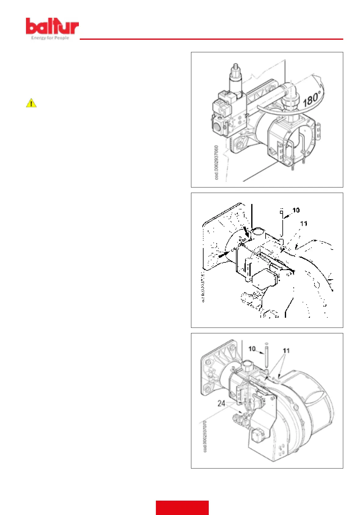
ASSEMBLY OF VENTILATION SYSTEM
Position the half-hinge on the burner scroll in line with those on the
combustion head assembly.
• Insert the hinge pin (10) in the position considered most suitable
• Connect the cables (switch on and ionisation) to the corresponding
electrodes, close the hinge, locking the burner by means of screws
(11).
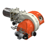
• Insert the gas throttle control lever on the shaft and block it with
the specic nut.
COMPLETING BURNER SETUP
• Remove the protective (yellow) caps from the ttings placed bene-
ath the head unit and near the solenoid valves.
• Connect the light oil pipes (24) provided with the burner to their
corresponding connectors, making sure they are properly sealed.
ENGLISH
11 / 42
0006160079_202008