GAS SUPPLY LINE
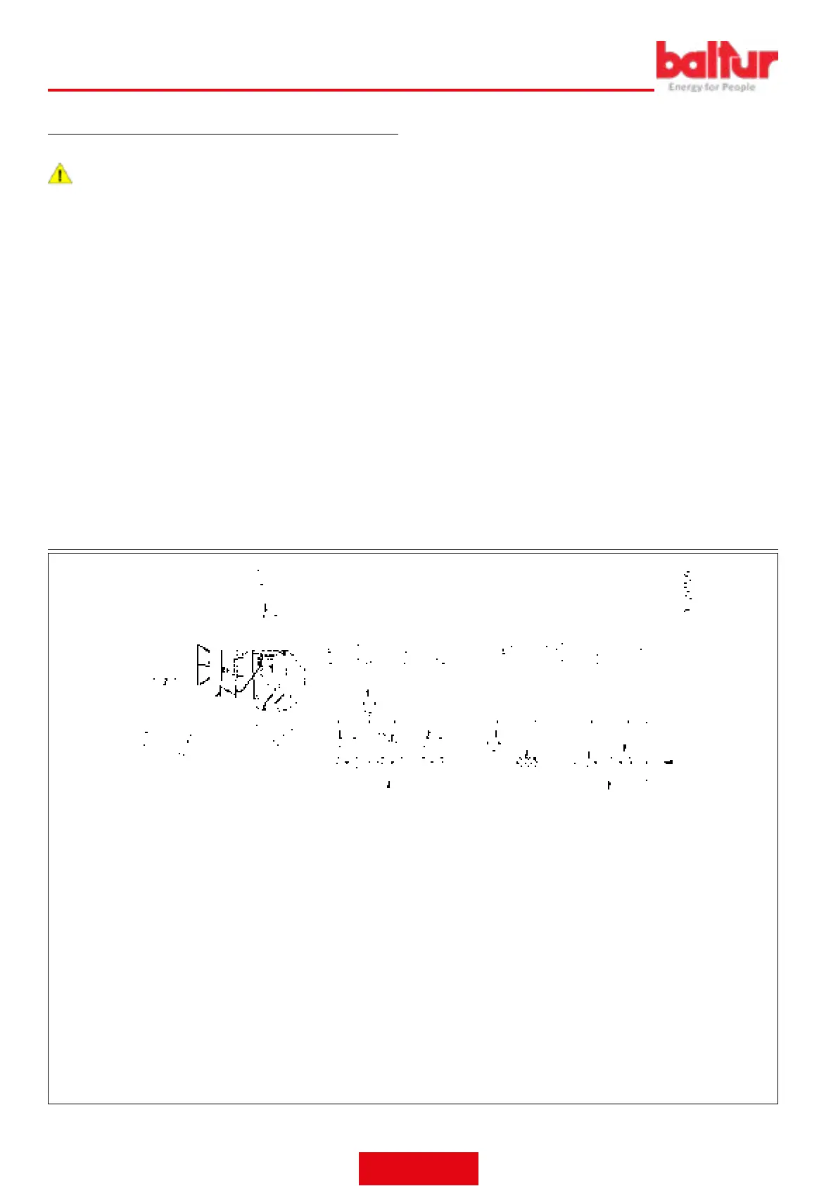
The gure below shows the gas supply line block diagram.
DANGER / ATTENTION
Install a manual shut-off valve and a vibration-proof joint
upstream of the gas valve, according to the layout shown in
the block diagram.
If the gas train is equipped with a pressure regulation device not in-
tegrated in a monoblock valve, follow the instructions below to install
the accessories on the gas pipe near the burner:
To avoid high pressure drops upon ignition, there should be a 1.5/2 m
long pipe section between the pressure reducer or stabiliser installa-
tion point and the burner.
The tube diameter should be equal to or greater than the burner at-
tachment union.
To ensure optimal operation of the pressure regulator, it should be
applied to the horizontal pipe after the lter.
The gas pressure regulator must be adjusted when it is working at the
maximum output actually used by the burner.
The delivery pressure must be adjusted to a level slightly below the
maximum obtainable.
GAS BURNER BLOCK DIAGRAM
GAS TRAIN SUPPLIED BY THE MANUFACTURER TO BE CARRIED OUT BY THE
INSTALLER
1 Manual shut-off valve
2 Vibration-proof joint
3 Gas lter
4 Minimum gas pressure switch
5 Safety valve
6 Pressure regulator
7 Valve seal control device (mandatory for burners with maximum rated heating capacity higher than 1200kW)
8 Slow opening working valve
9 Air/gas regulation servomotor
10 Air regulation damper
11 Air pressure switch
12 Combustion head
13 Gas regulation throttle valve
ENGLISH
12 / 42
0006160079_202008
 Loading...