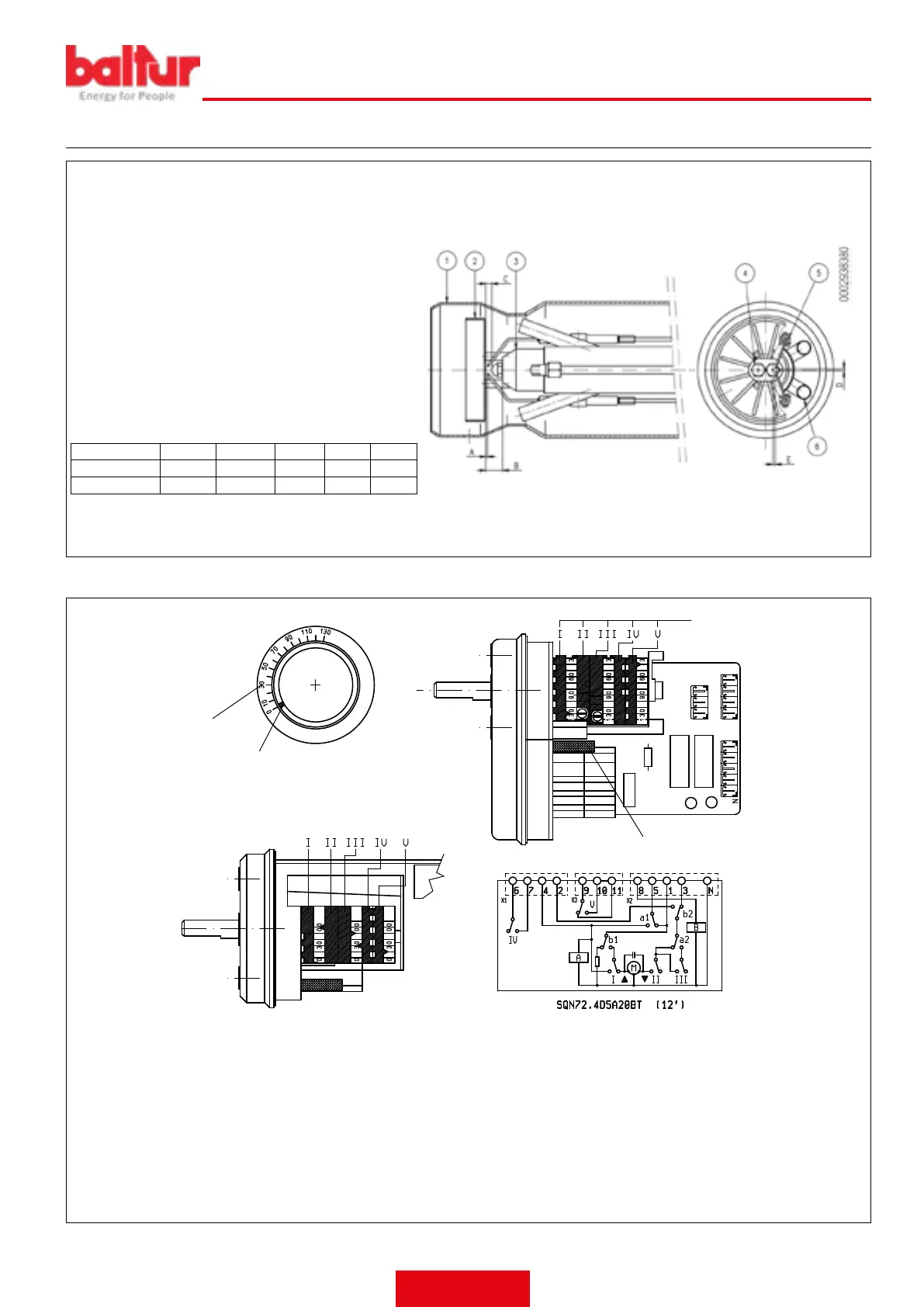
DIAGRAM FOR REGULATING THE COMBUSTION HEAD AND THE ELECTRODE DISK DISTANCE
After installing the nozzles, check the correct position of the
electrodes and disk according to the following measurements
indicated in mm.
It’s advisable to check the levels after every intervention on
head.
1 - Diffuser
2 - Flame disc
3 - Nozzle holder sleeve
4 - Diesel nozzle (No.2)
5 - Ignition electrode
6 - Gas nozzle (No.6)
Monarch type 45° PLP (TBML 90P)
Monarch type 45° SS (TBML 90P)
Monarch type 60° PLP (TBML 150P)
A B C D E
TBML 90P 1÷1,5 21÷22 8÷9 5÷6 7÷8
TBML 150P 1÷1,5 20÷21 7÷8 3÷4 8÷9
SERVOMOTOR CAMS ADJUSTMENT SQN72.4D5
1
2
3
4
0002938170
1 Reference scale
2 Position indicator
3 Motor-camshaft coupling On/Off pin
4 Adjustable camshaft
To adjust the setting of the cams used, use the corresponding rings
(I - II - III). The scale on the ring indicates the reference scale of the
rotation angle set for each cam.
I 2nd ame air regulation cam (130°)
II Total air closure (burner stopped) (0°)
III 1st ame air regulation cam (15°)
IV 2nd stage valve activation cam (30°).
V Unused cam
ENGLISH
29 / 42
0006160079_202008
 Loading...