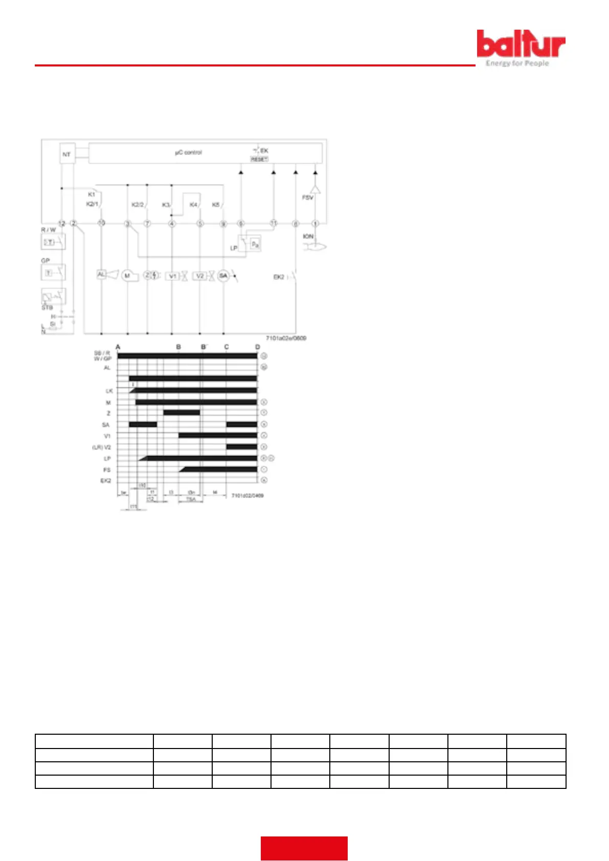
WIRING DIAGRAM AND OPERATION CONTROL SEQUENCE OF EQUIP-
MENT LME 22...
I 1st Actuator cam
t1 Preventilation time
t1´ Ventilation time
t3 Pre-ignition time
t3n After-ignition time
t4 Interval between ignition «Off» and release of «BV2»
t10 Available time for detecting the air pressure of the pressure switch
t11 Programmed opening time for actuator «SA»
t12 Programmed closing time for actuator «SA»
t22 2° safety time
TSA Ignition safety time
tw Waiting time
AGK25... PTC resistance
AL Error message (alarm)
BCI Burner Communication Interface
BV... Fuel Valve
CPI Closed Position Indicator
Dbr.. Wiring jumper
EK.. Remote lockout reset button (internal)
EK2 Remote lockout reset button
ION__tab_Ionisation probe
FS Flame Signal
FSV Flame signal amplier
GP Gas pressure switch
H Main switch
HS Auxiliary contactor, relay
ION__tab_Ionisation probe
K1...4 Internal Relays
KL Low ame
LK Air damper
LKP Air damper position
LP Air pressure switch
LR Modulation
M Fan motor
MS Synchronous motor
NL Rated load
NT Electric power supply
QRA... Flame Detection
QRC… Blue-ame detector bl blue br brown sw black
R Control thermostat / pressure switch
RV Gas adjustment device
SA SQN Actuator...
SB Safety limit thermostat
STB Safety limit thermostat
Si External fuse
t Time
W Limit thermostat / Pressure switch
Z Ignition transformer
ZV Pilot gas valve
A_tab_Start-up Command (ignition from «R»)
B-B´ Interval for ame ignition
C Burner in operation position
C-D Burner operation (generation of heat)
D Shut-down controlled by «R»
The burner will be immediately shut down
Burner control will be immediately ready for new start-up
Equipment or programmer TSA t1 t3 t3n t4 t11 t12
s s s s s s s
LME 22.233 C2 3 20 3 2,5 8 30 30
LME 22.331 C2 3 30 3 2,5 8 12 12
ENGLISH
32 / 42
0006160079_202008
 Loading...