Do you have a question about the Baofeng Pofung UV-5R and is the answer not in the manual?
Ensure the battery is fully charged before initial use.
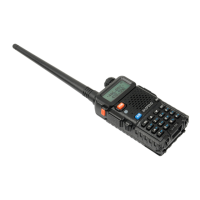
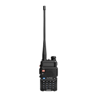
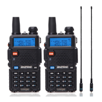
Securely connect the antenna to the radio unit.
Note key buttons like MENU, Arrows, EXIT, and specific color-coded keys.
Understand the 10-key pad and special keys for input and navigation.
Turn the radio on using the knob; it also controls volume.
Set the frequency step to the lowest setting via MENU options.
Choose the 'A' display mode using the blue A/B button.
Input the receive frequency 145115, noting the 5KHz step.
Adjusts the squelch level from 0 to 9.
Configures the frequency step size, with options from 2.5KHz to 25.0KHz.
Sets the transmit power level, with options for HIGH 4W and LOW 1 Watt.
Enables or disables the battery saving function.
Activates voice-activated transmission.
Selects between wideband and narrowband operation.
Controls the duration the display illumination remains active.
Enables or disables dual watch functionality.
Controls audible feedback for keypad presses.
Sets a timer to limit transmission duration.
Configures Digital Coded Squelch for receiving.
Configures Continuous Tone-Coded Squelch for receiving.
Configures Digital Coded Squelch for transmitting.
Configures Continuous Tone-Coded Squelch for transmitting, listing frequencies.
Enables or disables voice prompts.
Sets or displays the Automatic Number Identification.
Configures DTMF tones for transmission events.
Sets signal codes, often configured via computer.
Defines how the scanner resumes after a signal is detected.
Configures the PTT-ID transmission timing (BOT, EOT, BOTH).
Sets the delay for sending signal codes.
Configures the display mode for Channel A (Number, Name, FREQ).
Configures the display mode for Channel B (Number, Name, FREQ).
Enables or disables the busy channel lockout feature.
Activates or deactivates the automatic keypad lock.
Sets the direction of frequency shift for repeaters.
Specifies the frequency shift amount in MHz.
Stores current settings into a memory channel.
Deletes a stored memory channel.
Sets the backlight color for the standby display.
Sets the backlight color for the receive display.
Sets the backlight color for the transmit display.
Configures alarm modes: SITE, TONE, or CODE.
Selects between VHF and UHF bands.
Determines transmit selection based on display A or B.
Enables or disables squelch tail elimination.
Adjusts squelch tail elimination for repeater use.
Sets the delay for the repeater's squelch tail.
Configures the message displayed upon power-on.
Enables or disables the Roger Beep tone.
Restores radio settings to factory defaults.
Step-by-step guide for setting up a 2 Meter repeater with offset and CTCSS.
Instructions to clear memory and store VFO settings into a memory channel.
| Output Power | 4W / 1W |
|---|---|
| Battery Capacity | 1800 mAh |
| Channels | 128 |
| Modulation Mode | FM |
| Dimensions | 110 x 58 x 32 mm |
| Channel Spacing | 12.5/25 kHz |
| Operating Temperature | -20°C to +60°C |
| Antenna Connector | SMA-Female |
| Frequency Range | 136-174 MHz, 400-520 MHz |
| Antenna | Dual Band Antenna |
| Weight | 250g |
| Antenna Impedance | 50 ohm |
| Modulation | F3E |
| Operating Voltage | 7.4V DC |