4.2.1 ROTARY ACTUATOR TO ROTARY FUEL PUMP
4.2 TYPICAL LINKAGE ARRANGEMENTS FOR THE ACTUATOR AND FUEL SYSTEM
4.2.2 ROTARY ACTUATOR TO LINEAR FUEL PUMP
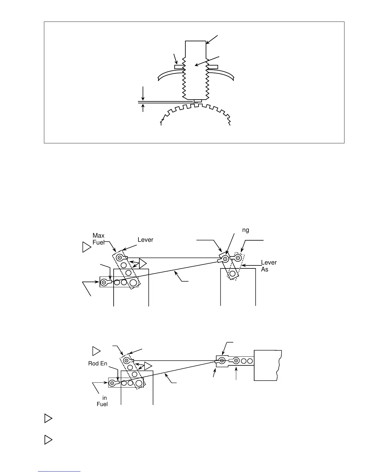
INSTALLATION OF MAGNETIC PICKUP
4.1.4 Mount the controller in the control panel.
4.1.5 Connect the wiring as shown in section 4.3 or according to your particular wiring diagram.
Speed Sensor
Ring Gear
Gap
.37 ± .127 mm
[.015 ± .005]
Magnetic Pickup
has 5/8-18 Threads
Jam Nut
2 Pin Connector
No.MS3106A 10-SL-4S
Engine
Housing
Actuator
Max
Fuel
Lever
Assembly
Min
Fuel
Rod End
Bearing
1
Fuel
Pump
Min
Fuel
Max
Fuel
Rod End
Bearing
Lever
Assembly
2
Rod
Actuator
Max
Fuel
Lever
Assembly
Min
Fuel
Rod End
Bearing
Rod
1
2
Min
Fuel
Max
Fuel
Rod End
Bearing
Fuel
Pump
Choose hole in actuator lever which causes actuator to rotate through its maximum rotation to provide
minimum to maximum fuel.
Non-Linear linkage to actuator is proper for best operation. Provides low GAIN at light loads and high
GAIN at heavy loads.
1
2
7

 Loading...