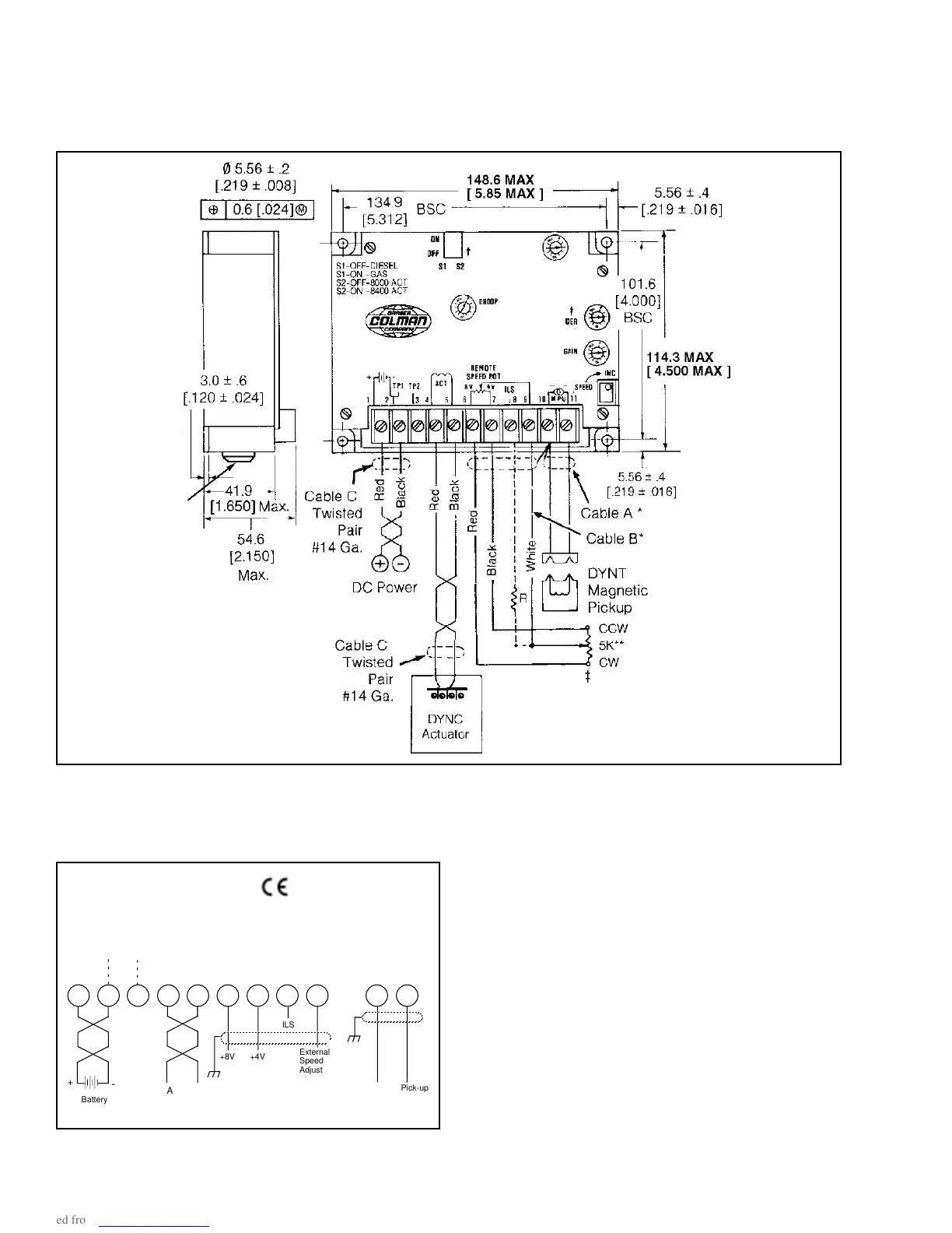
† The 5K remote speed potentiometer can be wired two different ways:
1. As shown by the solid line from the wiper of the 5K potentiometer
and then connected to terminal #9 (no resistor required). Adjust-
able range is approximately ±5% at 1800 RPM.
2. As shown by the dashed line from the wiper of the 5K potentiom-
eter through resistor R and then connected to terminal #8.
Reducing the value of R increases the remote adjustable speed
range.
8
Cable A -- DYNK-44-XX (specify length) (90° connector)
Cable B -- E26-22 (specify length)
Cable C -- DYNZ-70-4 (specify length) (terminal strip)
Cable C -- DYNK-210 (specify length) (MS connector)
* Shielded cable -- Should be purchased from Barber-Colman or
customer should purchase a cable with a wrapped mylar supported
aluminum foil shield with a drain wire.
** Remote speed potentiometer and 499K ohm resistor is B-C P/N
(DYNS-10000).
DIMENSIONS -- DYNA 8000 CONTROLLER -- DYN1 1065X and DYN1 1068X
Dimensions are in mm except as otherwise noted.
Dimensions in [ ] are in inches.
4.3 TYPICAL WIRING DIAGRAM & CONTROLLER INSTALLATION DIMENSIONS
TP1
1
2
3
4
5
6
7
8
9
10
11
TP2
Failsafe
+8V
+4V
ILS
External
Speed
Adjust
Chassis
Gnd
Screw
Chassis
Gnd
Screw
Blk
Wht
Magnetic Pick-up
+
-
Battery
Actuator
Wiring Diagram for Controllers
Chassis ground
screw
I

 Loading...